[phpBB Debug] PHP Warning: in file [ROOT]/includes/bbcode.php on line 483: preg_replace(): The /e modifier is no longer supported, use preg_replace_callback instead
[phpBB Debug] PHP Warning: in file [ROOT]/includes/bbcode.php on line 483: preg_replace(): The /e modifier is no longer supported, use preg_replace_callback instead
[phpBB Debug] PHP Warning: in file [ROOT]/includes/bbcode.php on line 483: preg_replace(): The /e modifier is no longer supported, use preg_replace_callback instead
[phpBB Debug] PHP Warning: in file [ROOT]/includes/bbcode.php on line 483: preg_replace(): The /e modifier is no longer supported, use preg_replace_callback instead
[phpBB Debug] PHP Warning: in file [ROOT]/includes/bbcode.php on line 483: preg_replace(): The /e modifier is no longer supported, use preg_replace_callback instead
[phpBB Debug] PHP Warning: in file [ROOT]/includes/bbcode.php on line 483: preg_replace(): The /e modifier is no longer supported, use preg_replace_callback instead
[phpBB Debug] PHP Warning: in file [ROOT]/includes/bbcode.php on line 483: preg_replace(): The /e modifier is no longer supported, use preg_replace_callback instead
[phpBB Debug] PHP Warning: in file [ROOT]/includes/bbcode.php on line 483: preg_replace(): The /e modifier is no longer supported, use preg_replace_callback instead
[phpBB Debug] PHP Warning: in file [ROOT]/includes/bbcode.php on line 483: preg_replace(): The /e modifier is no longer supported, use preg_replace_callback instead
[phpBB Debug] PHP Warning: in file [ROOT]/includes/bbcode.php on line 483: preg_replace(): The /e modifier is no longer supported, use preg_replace_callback instead
[phpBB Debug] PHP Warning: in file [ROOT]/includes/bbcode.php on line 483: preg_replace(): The /e modifier is no longer supported, use preg_replace_callback instead
[phpBB Debug] PHP Warning: in file [ROOT]/includes/bbcode.php on line 483: preg_replace(): The /e modifier is no longer supported, use preg_replace_callback instead
[phpBB Debug] PHP Warning: in file [ROOT]/includes/bbcode.php on line 483: preg_replace(): The /e modifier is no longer supported, use preg_replace_callback instead
[phpBB Debug] PHP Warning: in file [ROOT]/includes/bbcode.php on line 483: preg_replace(): The /e modifier is no longer supported, use preg_replace_callback instead
[phpBB Debug] PHP Warning: in file [ROOT]/includes/bbcode.php on line 483: preg_replace(): The /e modifier is no longer supported, use preg_replace_callback instead
[phpBB Debug] PHP Warning: in file [ROOT]/includes/bbcode.php on line 483: preg_replace(): The /e modifier is no longer supported, use preg_replace_callback instead
[phpBB Debug] PHP Warning: in file [ROOT]/includes/bbcode.php on line 483: preg_replace(): The /e modifier is no longer supported, use preg_replace_callback instead
[phpBB Debug] PHP Warning: in file [ROOT]/includes/bbcode.php on line 483: preg_replace(): The /e modifier is no longer supported, use preg_replace_callback instead
[phpBB Debug] PHP Warning: in file [ROOT]/includes/bbcode.php on line 483: preg_replace(): The /e modifier is no longer supported, use preg_replace_callback instead
[phpBB Debug] PHP Warning: in file [ROOT]/includes/bbcode.php on line 483: preg_replace(): The /e modifier is no longer supported, use preg_replace_callback instead
[phpBB Debug] PHP Warning: in file [ROOT]/includes/bbcode.php on line 483: preg_replace(): The /e modifier is no longer supported, use preg_replace_callback instead
[phpBB Debug] PHP Warning: in file [ROOT]/includes/bbcode.php on line 483: preg_replace(): The /e modifier is no longer supported, use preg_replace_callback instead
[phpBB Debug] PHP Warning: in file [ROOT]/includes/bbcode.php on line 483: preg_replace(): The /e modifier is no longer supported, use preg_replace_callback instead
[phpBB Debug] PHP Warning: in file [ROOT]/includes/bbcode.php on line 483: preg_replace(): The /e modifier is no longer supported, use preg_replace_callback instead
[phpBB Debug] PHP Warning: in file [ROOT]/includes/bbcode.php on line 483: preg_replace(): The /e modifier is no longer supported, use preg_replace_callback instead
[phpBB Debug] PHP Warning: in file [ROOT]/includes/bbcode.php on line 483: preg_replace(): The /e modifier is no longer supported, use preg_replace_callback instead
[phpBB Debug] PHP Warning: in file [ROOT]/includes/bbcode.php on line 112: preg_replace(): The /e modifier is no longer supported, use preg_replace_callback instead
[phpBB Debug] PHP Warning: in file [ROOT]/includes/functions.php on line 4752: Cannot modify header information - headers already sent by (output started at [ROOT]/includes/functions.php:3887)
[phpBB Debug] PHP Warning: in file [ROOT]/includes/functions.php on line 4754: Cannot modify header information - headers already sent by (output started at [ROOT]/includes/functions.php:3887)
[phpBB Debug] PHP Warning: in file [ROOT]/includes/functions.php on line 4755: Cannot modify header information - headers already sent by (output started at [ROOT]/includes/functions.php:3887)
[phpBB Debug] PHP Warning: in file [ROOT]/includes/functions.php on line 4756: Cannot modify header information - headers already sent by (output started at [ROOT]/includes/functions.php:3887)
Tractorsport Flowbench Forum Archive • View topic - DIY Inclined Manometer

DIY Inclined Manometer

Discussion on general flowbench design

Postby bruce » Tue Dec 28, 2004 3:07 pm

Ok, finally had sometime this week to start playing with a simple (?) inclined manometer based on common parts avaliable in my local hardware store.

First off I've come to the conclusion that yes you can build a simple inclined manometer, second your level of accuracy is simply going to give you a comparison of numbers based on your own bench.

Let me also state, This is for a pitot style of bench and is very open for discussion on this forum. The whole goal of this project is so the DIY'er can build something simple and accurate for their use, its not intended for laboratory grade testing

Let me run down what I have come up with so far; My manometer is based on a 6" rise over a meter stick scale this allows you to see 1000 divisions so each division equals .006". I used Marvel Mystery oil for my fluid since it is red in color, this has a specfic gravity of .9 (correction the specific gravity is .830) based on the MSDS. So based on this specific gravity the scale has to have a rise of 6.66 to compensate for the weight difference between water. Well this is how its suppose to work anyways.

The inlined tube is clear acrylic with an internal dia of .187 my well dia is around 2" (I forgot to measure it, I'll get that measurement later) I want to compare different size well diameters to see if there is any effect on the readings?

I'm thinking calibration is going to be the problem? My plan is to setup the inclined manometer based on comparing just static readings between the vertical static and the inclined static pressures without the velocity hooked up. So if I draw 4" on the vertical the inclined will also show the same reading in static on its scale? I can do this at various readings to compare my calibration.

Here are some pics of the basic setup, this should give everyone enough of an idea of what I am looking at.

Image
Image


Edited By bruce on 1105236861
"There is no more formidable adversary than one who perceives he has nothing to lose." - Gen. George S. Patton
bruce
Site Admin
 
Posts: 1638
Joined: Sun May 09, 2004 12:17 pm

Postby 84-1074663779 » Tue Dec 28, 2004 4:50 pm

Sounds pretty good Bruce. The potential accuracy you will get depends mostly, on how accurately you can construct it.

With such a long scale and small rise, keeping the acrylic tube dead straight will definitely require some sort of continuous mechanical support along its entire length. It tends to sag by itself, if not immediately, it probably will over time.

The other difficulty is keeping the whole thing sufficiently level. Six thou is not much over such a long length of tube. Probably best to bolt the manometer board permanently to a brick wall.

Vertical manometers suffer neither of these problems, but the shallower the angle of slope, the more care that needs to be taken in construction and setting up.

With the well, the important thing is the relative surface area of tube and well. One goes up while the other goes down. The volume of fluid in the well is irrelevant, only the relative surface areas matter. So make the well as wide and shallow as possible.

I was once given the problem of providing an easily read height readout for a hospital X ray machine. The patient lay on a table which could be electrically raised and lowered by the Radiologist. What I did was fit an ordinary transparent plastic ruler to the table that passed through the optical path of a cheap slide projector. The ruler scale in millimeters was projected onto a nearby wall.

The display on the wall was huge, very bright and clear, and perfectly in focus. I have not tried it, but I wonder if a small rise vertical manometer could be projected somehow to make the scale appear much longer and easier to read ?

Probably a crazy idea, anyone game to try it ?
84-1074663779
 

Postby hollywood63 » Wed Dec 29, 2004 10:29 am

Bruce,
The incline that I'm building is almost exlactly like yours except for the scale. But I seem to be getting extremely confused when it comes to the correct operation of a incline manometer
Here is what I did on mine the scale is 0-28" I have a rise of 7.5"
my small tubing is .250 .id and my well is 3" .id. How I came up with these measurements is from a spreadsheet that was posted by rocco. You punch in the tube .id the well id the length of the scale and the height of the scale it then computes out the scale markings for you and what angle the scale should be at.
Let me explain the way I understand all of this to work.
You have a test orfice like the one you made for me. Start the bench up with the orfice in place and set your test pressure. .ie 8-10 or 28 " or what ever your bench will pull. Now on the incline scale in my case 28" long I should be reading at the 28" line pulling 28" on the vertical manometer. I remove the orfice install a head and compare my readings from the head to the know number from the test piece.
I have looked on the net for incline manometer operation and all is I do is confuse myself even more hence this reply. I'm sorry if I hijacked your post this is not my intention if you need to move this fell free your the boss.
Thanks Art
hollywood63
 
Posts: 59
Joined: Mon Nov 15, 2004 10:25 pm
Location: U.P of Michigan

Postby bruce » Wed Dec 29, 2004 11:05 am

How did you come up with 0-28"? Your scale rise is only 7.5" How long is the inclined tube? This is the working length of your manometer. Your scale should have equal divisions across this length if you are using it with a pitot setup. AN orifice bench would use a percent scale on the other hand.

No problem on "hijacking", the forum is to pass along info not to be politically correct :) I'm not the "boss" I just host the forum, I'm in know way the most knowledgable, but do help the collective database out a bit.

Can you point me to the post with the spreadsheet on it?
"There is no more formidable adversary than one who perceives he has nothing to lose." - Gen. George S. Patton
bruce
Site Admin
 
Posts: 1638
Joined: Sun May 09, 2004 12:17 pm

Postby 86rocco » Wed Dec 29, 2004 1:07 pm

I'll have to post a picture of my prototype manometer when I get my camera back. It's for a orifice type bench, the scale is calibrated in % of maximum flow i.e. for each particular orifice, 100% will be calibrated as particular number of CFM@ 28" depending on size and the calibration number is used as a multiplier for the reading on the inclined manometer to give a flow number. The advantage of doing it this way besides making the arithmetic simple is that I don't need to worry about the well to tube diameter ratio because that ratio is constant and because I'm not concerned about getting an actual pressure reading, all I need is the percentage.

The manometer itself is a rigid acrylic tube 1/8" i.d about 30" long, the well is the body of a syringe. It has a few interesting features, it has a secondary reservoir which makes filling simpler and that reservoir also has a moveable plunger in it to change the volume via a thumb screw, this serves to accurately zero the scale. for the final version I plan to have the well and reservoir machined out of a single block of clear arcylic.
86rocco
 
Posts: 319
Joined: Fri Mar 12, 2004 9:11 am

Postby Rick360 » Wed Dec 29, 2004 3:18 pm

You can calculate the offset to the well rise to correct for the well size if the well has constant surface area over the range the fluid will be at.

(Tube inside area * scale length)/Well inside area

This will tell you the rise in level in the well over the scale length of fluid movement. You can adjust your rise (lower) by this amount.
For Bruce's manometer
.187" id tube = .027464588 sq in
2" well = 3.14159... sq. in.
scale = 1meter = 39.37"
(.027464588 * 39.37)/3.14159 = .344"
6.66"-.344" = 6.316" rise

I also like a loop in the lower tube to prevent sucking it dry if you over pressure by a little bit.

Why do you say this is for a pitot type bench? This is the same way I built mine for a orifice bench. I marked the scale off in % of flow, but you could use a ruler and calculate from there if desired. Should work either way.

I'll try to post a pic of mine when I get home tonight.

Rick
Rick360
 
Posts: 58
Joined: Tue Dec 14, 2004 8:41 pm
Location: MO

Postby 84-1074663779 » Wed Dec 29, 2004 5:14 pm

Art, it certainly can be confusing until basic operation is understood.

The first thing is that the pressure drop across any orifice increases as the square of the airflow. If it has a certain pressure drop at a certain flow, doubling the flow would cause the pressure drop to increase four times. Tripling the airflow volume causes the pressure to increase nine times. That is the basis of operation of any measurement orifice.

So you have your orifice, and you need a measurement manometer of some sort connected across it to measure pressure differential.

The first thing that needs to be decided is what sort of pressure range is going to be used with that orifice. It could be anything from a couple of inches to tens of inches, it mainly depends on available blower power. Lets say you have decided to operate your flow measurement orifice up to a maximum of 7.5 inches pressure drop, and you know the calibration airflow figure at that pressure.

So full scale flow ( xxx Cfm) can be 100% at 7.5 inches.

Using the square law rule we know that doubling the flow increases pressure four times, so: flow x flow = pressure

We can now mark out a suitable manometer scale going from say 50% flow to 100% flow

50% flow (0.5) 0.5 x 0.5 = 0.25 0.25 of 7.5" is 1.875 inches rise
60% flow (0.6) 0.6 x 0.6 = 0.36 0.36 of 7.5" is 2.700 inches rise
70% flow (0.7) 0.7 x 0.7 = 0.49 0.49 of 7.5" is 3.675 inches rise
100% flow (1.0) 1.0 x 1.0 = 1.0 7.500 inches rise

So we now have a scale that goes from 1.875 inches at 50% flow to 7.5 inches at 100% flow.


This same scale can be used with any sized orifice. If one orifice flows 17 Cfm at 7.5 inches, just read the percentage flow directly off the scale. A much larger orifice might flow 631 Cfm at 7.5 inches, again just read the percentage off the scale and multiply by 631 to get actual Cfm flow.

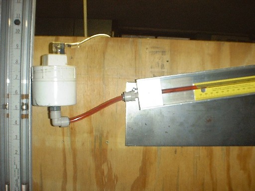
The problem with this is that the scale length is only 7.5 inches long with a vertical manometer and difficult to read.

The developed air pressure will still raise the water 7.5 inches, but by inclining the manometer it travels further along the scale.

The manometer tube can be any length you want to make it, but as long as the high end is 7.5 inches higher than the well it will work exactly the same.

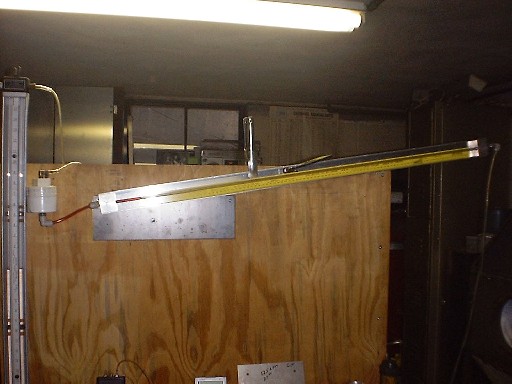
If you wanted to make the tube 20 inches, 28 inches, or 1000mm, it does not matter. Incidentally, 1000mm is a convenient length and very easy to mark off. It is a lot easier to find 706mm on a steel ruler than 17.93 inches !

Lets suppose you have a manometer scale 1000 mm long and it is marked off in flow increments from say 50% flow at 250mm to 100% flow at 1000mm. That same scale can be used at any desired orifice operating pressure by raising the high end the desired amount.

If you decide to do all your flow measurements at a 100% calibration pressure of fifteen inches of water, just raise the 100% mark on the scale 15 inches above the well height.

The ANGLE of slope is irrelevant, it is only the height of the high end that matters, and you can make the scale length anything that is convenient to construct.

The well is important because as the fluid rises along the manometer tube, it falls in the well. So at zero pressure both fluid levels will be the same. At full pressure the well will always have fallen.

If your manometer rise is say nine inches, and the well falls a quarter inch, the rise may really be nine and a quarter inches, so beware of this error. Fixing it only requires dropping the high end a bit to compensate, or making the well have a larger surface area.

It is all fairly obvious once you have thought it all through. It is all just a bit confusing at the start.

If your test pressure is 28 inches, and your flow manometer operates at 7.5 inches, your blower must provide sufficient air to operate at the combined pressure drop of 35.5 inches. This might be a tall order. It is why lower pressures and sloping manometers are used.

If you have a mighty blower that can operate at 60 inches or more pressure, the flow manometer can be mounted vertical, it does not have to slope.
84-1074663779
 

Postby bruce » Wed Dec 29, 2004 6:08 pm

Ok so as not to confuse Art anymore than he probably already is I want to clarify what type of bench he is using. The orifice he has is a calibration plate for on top of his bench, his actual bench he is building is an annubar setup.

I'm confused myself on what is what anymore UGH!! :)

For a pitot design bench you need numbers not percent to do the calculations. The numbers from the manometer along with the surface area of the test tube is used to get CFM's. Hope this clears everyone up?

For those of use who have been around this for awhile "playing" its not confusing . . . well not much anyways. Its getting the accuracy thats the problem using none accurate materials.

PS Tony my clear acrylic tube is kept tight with a tension nut on one end that keeps the tube tight along its length. I'll get a good pic of it and post it in the near future.
"There is no more formidable adversary than one who perceives he has nothing to lose." - Gen. George S. Patton
bruce
Site Admin
 
Posts: 1638
Joined: Sun May 09, 2004 12:17 pm

Postby Rick360 » Wed Dec 29, 2004 10:51 pm

Image

Here is my manometer. Rigid (acrylic i think) clear plastic tubing. It can be heated and bent quite easily. The well is a air cylinder I had for a uniform machined ID.

I don't know why a manometer would be different for pitot tube or orifice. The full scale flow could be calculated for a pitot and that would be 100% of the scale. Any other place just read % and mult. by full scale, provided the scale is in % flow (square root of DP). Measured scales could be used for a orifice bench too. Just different calcs needed.
Rick360
 
Posts: 58
Joined: Tue Dec 14, 2004 8:41 pm
Location: MO

Postby hollywood63 » Wed Dec 29, 2004 11:00 pm

WOW Thanks everyone for all of the info if I don't respond to all of the questions right away I have to save all of this info and let it sink in. Sorry for not explaining my bench type. I did not know that a annubar type did not use a % scale and I'm not even going to ask why :p just yet :D .
Thanks Again
hollywood63
 
Posts: 59
Joined: Mon Nov 15, 2004 10:25 pm
Location: U.P of Michigan

Postby bruce » Wed Dec 29, 2004 11:27 pm

You're probably correct Rick and Tony on the percent, my mind doesn't think percent of flow though sorry bout that :)

How do you compensate for air changes with a percent scale from test to test? On the pitot you have a correction factor for doing your CFM calculations. Do you apply a correction factor on the orifice bench? This might already be covered in the other forums somewhere . . .
"There is no more formidable adversary than one who perceives he has nothing to lose." - Gen. George S. Patton
bruce
Site Admin
 
Posts: 1638
Joined: Sun May 09, 2004 12:17 pm

Postby Rick360 » Thu Dec 30, 2004 1:08 am

Rick360
 
Posts: 58
Joined: Tue Dec 14, 2004 8:41 pm
Location: MO

Postby 84-1074663779 » Thu Dec 30, 2004 1:44 am

Rick is right, no corrections needed.

To understand this, think of your cylinder head as a restriction, and your orifice plate as a restriction. The air that flows through both is the very same air.

Whatever factors effect flow through the head will also effect flow through the measurement orifice in exactly the same way. That is the beauty of the method. It is ratiometric.

If you measure 81% flow on a scorching midsummers day, you will also measure 81% flow on a freezing midwinter night six months later. That is really all you need to know.

If you do a bit of port modification and can get 91%, you know things are getting better. The actual CFM are probably less important than repeatability, and being able to accurately measure small changes.
84-1074663779
 

Postby jim fuchs » Thu Dec 30, 2004 7:33 pm

do thay make a fluid that will work in a non heated shop ..jim
jim fuchs
 
Posts: 13
Joined: Sun Dec 05, 2004 7:40 pm
Location: iowa

Postby hollywood63 » Sun Jan 02, 2005 9:29 am

Happy New Year everyone,
I picked 0-28 scale because thats what seems to be common. I understand that I have a 7.5 rise but by inclining the manometer I have more resolution and will be able to see smaller improvments. (I hope thats correct :D ) I have a steel ruler that is 28 inches long and using the spreadsheet that I sent Bruce I can find my percentage of flow. Maybe you can post the sheet for whatever reason I can't seem to post a attachment.
My manometer is setup like the one in ricks photo. Just beacuse thats were the 0 is on the scale. If I'm correct it doesn't matter if the zero is on the high or low side.
I think were I'm getting confused is I have to flow my test piece at whatever test pressure I decide to use and then make my incline scale??? I know what this piece flows on someone elses bench but I have to calibrate my bench to this piece since thats going to be my standard to go from or am just chasing my tail again
Art
hollywood63
 
Posts: 59
Joined: Mon Nov 15, 2004 10:25 pm
Location: U.P of Michigan

Next

Return to Flowbench General

Who is online

Users browsing this forum: No registered users and 2 guests

cron