
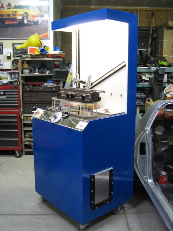
OK, I have been reading this board for a year and now have built the flowbench with my friend's help that I collected parts for when the MSD article came out. It has been fun and looks great. But, I do not feel comfortable with the numbers we are getting. The leakage checks out at 9 cfm due to leakage through the motor and light switches (when covered we only have 2 cfm leakage).
I then put a 1.75 dia orfice on the bench and using orfice #4 (1.75 dia), I get 98.4% flow at 13" of test pressure. This seams right until I think about the leakage. Should I not get over 100% by the amount of leakage?
We then tried to flow a head and the numbers are high on the first two or three orfices then they are slightly high on the larger orfices. An example: @ .100 lift on orfice #3 (104cfm) at 28" we got 94% which = 98cfm - leakage (was 12 cfm with head on) = 86 cfm. Immediately changed to next orfice up #4 (180 cfm) got 49.5% which = 89 cfm - leakage = 77 cfm. Can the orfices be off 9 cfm or 10%? The best ported head of this kind we have seen flow numbers for flows 70 cfm. So the bench is at least 7 to 16 cfm high.
Why do the cfm and orfice dimensions in the MSD article not work using the flow calculations? The first two look good but they get farther off as you go up.
On our bench with a somewhat known head, the flow numbers down low are high ~20-25% and just slightly high on up ~10%.
Is there a calibration procedure out there for dummies? Do we need to use a calibration factor for each orfice or is one good for all orfices? Does this need to be also done for exhaust with different calibration factors?
How far off can a orfice plate be in cfm if it has the same hole size, say 1.75 +/-.002, and is .090 thick?
Sorry for the long post but this thing is driving both of us crazy. Thanks for any help you can give!
Flowbench Calibration for Dummies! - Flowbench Calibration for Dummies!
24 posts
• Page 1 of 2 • 1, 2
![]() by bruce » Wed Mar 14, 2007 5:29 pm
by bruce » Wed Mar 14, 2007 5:29 pm
We just had an extensive thread that dealt with another forum member having problems with his calibration, take some time to review this thread in detail and follow along with how he made out on calibration.
There are so many variables to deal with when it comes to this subject. One I always ask is the quality of the orifice plates, are they sharp edge or square edge plates? If you say they are +/-.002" they are not the same hole size then? The accuracy and quality of the edges plays alot with the Cd the plate ends up having.
I'm sure others here will address this post in more detail than I have . . . but the link I posted will give you a good idea of what is involved in tracking down your calibration.
"There is no more formidable adversary than one who perceives he has nothing to lose." - Gen. George S. Patton
- bruce
- Site Admin
- Posts: 1638
- Joined: Sun May 09, 2004 12:17 pm
![]() by Thomas Vaught » Thu Mar 15, 2007 9:15 pm
by Thomas Vaught » Thu Mar 15, 2007 9:15 pm
Getting "close" is just the first step in building a bench. The msd orifice calculations for flow were
average at best. The real trick and a lot of fun is getting the last few cfm to line up properly. Most
Flow bench manifacturers will have a spec sheet for each machine they create and even then they will only guarantee the bench to 1% of flow
accuracy. 1% of a 300 cfm orifice is 3 cfm.
If you want to read very close to what Bruce and some others read then get some of Bruce's calibration orifice plates. They may not match the 3 million dollar bench exactly but they are surprisingly (for the low cost) very close.
JMO
Tom V.
- Thomas Vaught
- Posts: 465
- Joined: Fri Feb 18, 2005 5:36 pm
- Location: Michigan
![]() by bpowell » Fri Mar 16, 2007 10:03 am
by bpowell » Fri Mar 16, 2007 10:03 am
Thanks guys, we were derailed but the thread bruce mentioned helped get us back on track. First thing was to connect our manometers together, here's what we did:
1. Disconnected our manometers from our valves then "T'ed" them together.
2. The third leg (tube) was routed to the head fixture (top side of the orifice), and left the other ends of the manometers open to atmosphere.
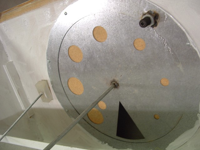
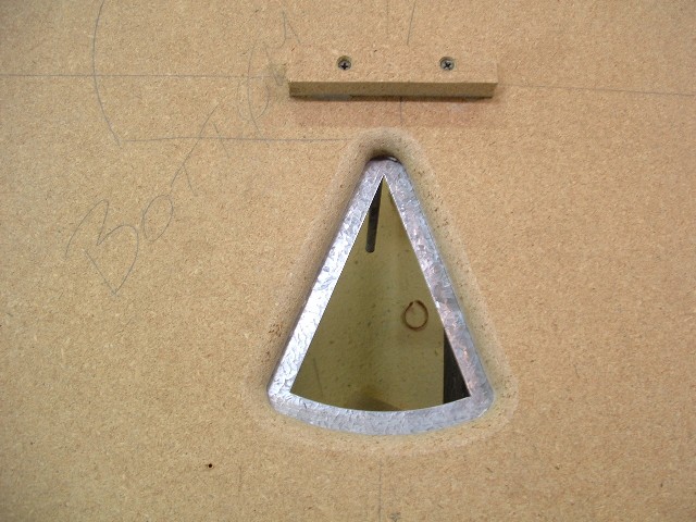
3. We selected our smallest orifice (.625" ID), and blocked off our head fixture (picture shows head instead).
4. Turned on (4) of our (8) motors and opened our bowl valve to various test pressures.
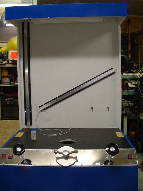
I will attempt to post a picture to help visualize our set-up. Initially our inclined manometer was positioned for a 13" rise over a length of 29.07". Our reservoir is 1.5" ID and our tubing is 1/8". Using this data, we compared our manometers to the excel spreadsheet posted on this site results and were consistently a little off, here's the initial data...vs. spreadsheet:
100%=13.675"...13.2 (spreadsheet)
86%=10.225"...9.76
34.5%=1.75"...1.57
Overall average = 6.5%, off compared to chart.
It was difficult to get good recorded data due to the steady but slow decline in pressure. Any idea what this is? We figure either the bowl is moving around or our used motors are being pulled down (bad brushes one motor and another not up to par with the other two being used?).
We then adjusted our incline manometer height to more closely match our vertical water head. We started the motors and adjusted the incline manometers height to match 100% to 13" wc on the vertical manometer. Our new incline height is now 12.344". We reset our vertical height scale values in the spreadsheet, re-positioned our reservoir for zero level and re-tested. Here's what we got:
75%=7.25"...7.05
50%=3.25"...3.14
25%=.75"... .78
Overall average = 3.4% off compared to chart.
Should we leave the incline at the new angle, or are there other issues we should address? Both the manometers continued to slowly go down throughout each test pressure making is harder to get accurate data when T'd together but worked normally when correctly plumbed- no dropping of wc at steady state.
We then did a leakage check, and got 10.5 cfm, most of this (we figure 8 cfm) is through the panel switches themselves. This leakage was calculated from an incline manometer reading of 37.5% @ 28" test pressure on the .623" OD orifice. This orifice is supposed to be 28 cfm at that pressure (.375x28).
One thing we also noticed, our 1/4" threaded rods that control our bowls twist easily when seating or unseating the bowls. We did add 1/4" thick aluminum plates on each side of the bowls (for clamping) to minimize flutter due to somewhat flimsy bowls.
1. Disconnected our manometers from our valves then "T'ed" them together.
2. The third leg (tube) was routed to the head fixture (top side of the orifice), and left the other ends of the manometers open to atmosphere.
3. We selected our smallest orifice (.625" ID), and blocked off our head fixture (picture shows head instead).
4. Turned on (4) of our (8) motors and opened our bowl valve to various test pressures.
I will attempt to post a picture to help visualize our set-up. Initially our inclined manometer was positioned for a 13" rise over a length of 29.07". Our reservoir is 1.5" ID and our tubing is 1/8". Using this data, we compared our manometers to the excel spreadsheet posted on this site results and were consistently a little off, here's the initial data...vs. spreadsheet:
100%=13.675"...13.2 (spreadsheet)
86%=10.225"...9.76
34.5%=1.75"...1.57
Overall average = 6.5%, off compared to chart.
It was difficult to get good recorded data due to the steady but slow decline in pressure. Any idea what this is? We figure either the bowl is moving around or our used motors are being pulled down (bad brushes one motor and another not up to par with the other two being used?).
We then adjusted our incline manometer height to more closely match our vertical water head. We started the motors and adjusted the incline manometers height to match 100% to 13" wc on the vertical manometer. Our new incline height is now 12.344". We reset our vertical height scale values in the spreadsheet, re-positioned our reservoir for zero level and re-tested. Here's what we got:
75%=7.25"...7.05
50%=3.25"...3.14
25%=.75"... .78
Overall average = 3.4% off compared to chart.
Should we leave the incline at the new angle, or are there other issues we should address? Both the manometers continued to slowly go down throughout each test pressure making is harder to get accurate data when T'd together but worked normally when correctly plumbed- no dropping of wc at steady state.
We then did a leakage check, and got 10.5 cfm, most of this (we figure 8 cfm) is through the panel switches themselves. This leakage was calculated from an incline manometer reading of 37.5% @ 28" test pressure on the .623" OD orifice. This orifice is supposed to be 28 cfm at that pressure (.375x28).
One thing we also noticed, our 1/4" threaded rods that control our bowls twist easily when seating or unseating the bowls. We did add 1/4" thick aluminum plates on each side of the bowls (for clamping) to minimize flutter due to somewhat flimsy bowls.
- bpowell
- Posts: 17
- Joined: Tue Mar 13, 2007 4:07 pm
![]() by Thomas Vaught » Sat Mar 17, 2007 3:05 pm
by Thomas Vaught » Sat Mar 17, 2007 3:05 pm
Boy! That is the nicest MSD type bench I have seen in a while. Tom V.
- Thomas Vaught
- Posts: 465
- Joined: Fri Feb 18, 2005 5:36 pm
- Location: Michigan
![]() by bpowell » Mon Mar 19, 2007 9:59 am
by bpowell » Mon Mar 19, 2007 9:59 am
I have to give props to my friend Craig who got this whole project started, without him all of the pieces I had collected years ago would still be in their boxes. Tom- thanks, but I would rather it was accurate than look good. We sealed up a couple of leaks this weekend but still are having a time with the manometers. Can someone explain why when we t'd the manometers together we get different readings? At 13" test pressure the incline manometer should have been 100% (13" rise). We had to reduce the incline angle to 12 1/4" to get 100%. This does not seam right, any ideas?
- bpowell
- Posts: 17
- Joined: Tue Mar 13, 2007 4:07 pm
![]() by bruce » Mon Mar 19, 2007 1:33 pm
by bruce » Mon Mar 19, 2007 1:33 pm
Surface area of the well verses the tube dia on your inclined manometer? The U tube has the same "wells" your inclined manometer has a well dia of ?? and a tube dia of ?? so they are different. Just a quick thought . . .
"There is no more formidable adversary than one who perceives he has nothing to lose." - Gen. George S. Patton
- bruce
- Site Admin
- Posts: 1638
- Joined: Sun May 09, 2004 12:17 pm
![]() by Thomas Vaught » Mon Mar 19, 2007 6:20 pm
by Thomas Vaught » Mon Mar 19, 2007 6:20 pm
In your pictures, I see one picture with no well manometer for the inclined manometer. In a second picture, I see a well for the manometer BUT it looks to me like your well is below the end of the scale (where the zero would be). It may be on the zero but the pics are not that clear.
The well should be at the same height as the zero point on the scale. You then can assume that any reduction in the 13" of height is made up by the rise in the well. Example .300" rise in the well plus say 12.7" in the rise of the incline.
JMO
Tom V.
The well should be at the same height as the zero point on the scale. You then can assume that any reduction in the 13" of height is made up by the rise in the well. Example .300" rise in the well plus say 12.7" in the rise of the incline.
JMO
Tom V.
- Thomas Vaught
- Posts: 465
- Joined: Fri Feb 18, 2005 5:36 pm
- Location: Michigan
![]() by bpowell » Mon Mar 19, 2007 10:26 pm
by bpowell » Mon Mar 19, 2007 10:26 pm
We are still plugging away at it....
We tried sealing our switches with silicone this weekend only to find out tonight that the switches have continuity regardless of switch position Time to tear the sealed control panel off again.
We also had a couple of motors that were down on power, they looked like little green flame throwers in the dark. We replaced the brushes on one of the two motors and crossed our fingers.... it worked, full power returned! We just need brushes for the other weak motor now.
Tom, we do keep the well adjusted to zero but in the picture we have the level in the container a little high (into the smaller diameter of the well). We removed some of the water and re-adjusted the well up to compensate.
Bruce, both the vertical and inclined manometers contain 1/8" tubing.
Does it matter that our vertical manometer is connected midway (height wise) in the acrylic head fixture (see first picture, you can barely see it in the back)? I've seen several benches where this connection was made to the enclosure, this side of the orifice plate. The reason I ask is we are still having trouble maintaining constant levels (they drift up and down) when trying to adjust to a specific pressure or percentage. Both manometers do move in unison but it movement up and down makes it hard to get a good read.
Thanks
We tried sealing our switches with silicone this weekend only to find out tonight that the switches have continuity regardless of switch position
We also had a couple of motors that were down on power, they looked like little green flame throwers in the dark. We replaced the brushes on one of the two motors and crossed our fingers.... it worked, full power returned! We just need brushes for the other weak motor now.
Tom, we do keep the well adjusted to zero but in the picture we have the level in the container a little high (into the smaller diameter of the well). We removed some of the water and re-adjusted the well up to compensate.
Bruce, both the vertical and inclined manometers contain 1/8" tubing.
Does it matter that our vertical manometer is connected midway (height wise) in the acrylic head fixture (see first picture, you can barely see it in the back)? I've seen several benches where this connection was made to the enclosure, this side of the orifice plate. The reason I ask is we are still having trouble maintaining constant levels (they drift up and down) when trying to adjust to a specific pressure or percentage. Both manometers do move in unison but it movement up and down makes it hard to get a good read.
Thanks
- bpowell
- Posts: 17
- Joined: Tue Mar 13, 2007 4:07 pm
![]() by bruce » Mon Mar 19, 2007 10:43 pm
by bruce » Mon Mar 19, 2007 10:43 pm
Try moving your static pickup to the plenum area and see if it becomes more stable, I would venture to say that it will.
"There is no more formidable adversary than one who perceives he has nothing to lose." - Gen. George S. Patton
- bruce
- Site Admin
- Posts: 1638
- Joined: Sun May 09, 2004 12:17 pm
![]() by bruce » Tue Mar 20, 2007 1:26 pm
by bruce » Tue Mar 20, 2007 1:26 pm
I'd go with "B" . . . someone else with more experience on orifice benches will be able to answer the orifice location question better than I can. But I would say it looks good, since it is not a direct shot for the airflow into the orifice.
"There is no more formidable adversary than one who perceives he has nothing to lose." - Gen. George S. Patton
- bruce
- Site Admin
- Posts: 1638
- Joined: Sun May 09, 2004 12:17 pm
![]() by bpowell » Tue Mar 20, 2007 4:18 pm
by bpowell » Tue Mar 20, 2007 4:18 pm
Bruce- did you get a chance to make the orfices this weekend? Please be sure to check them against the PAP's. Let me know how much I owe and how to send it.
I was wondering if I should tee the tube running into the upper chamber that goes to the incline manometer and used it also for the test pressure manometer. Then, both would get the same signal eliminating the positioning variable. I can try this easy enough but thought I would ask the experts. I think if we get this manometer issue resolved and get the calibrated orfice plates, we should be ok.
I am unsure of how the manometers should be tied together for calibration. We put a tee between the incline manometer upper end (other end open), the test pressure manometer (other end open) and the source being the test pressure port in the head adapter. Is this correct? Should we do this test with the manometers in series? If so, which one closest to the pressure/vaccuum source?
- bpowell
- Posts: 17
- Joined: Tue Mar 13, 2007 4:07 pm
![]() by 200cfm » Tue Mar 20, 2007 9:26 pm
by 200cfm » Tue Mar 20, 2007 9:26 pm
Yes, B is a better probe pickup point. And yes, it is ok to "T" the common upper chamber to the proper port of the test and incline manometer. The tracking is better when they share a common "T". from my experience. What size is your pickup probe? I used a very small brass tube with tiny holes drilled around the tube. And hung a small rubber hose over it to serve as a shield or "minature hat" to guard against any direct air velocity turbulence or air swirl contact. When things are right the manometers will be surprisingly steady.
- 200cfm
- Posts: 302
- Joined: Fri Nov 17, 2006 10:52 pm
- Location: Virginia
24 posts
• Page 1 of 2 • 1, 2
Who is online
Users browsing this forum: No registered users and 3 guests