
I have a few questions about how y'all have your test fixtures set up for pressure testing.
First a little background:
We have a bi-directional Pitot style bench with an FP1 Flow Processor. We are flowing over 1000 CFM on the 4" range - the bench works very well. We have 16 motors staged in banks of 2, we have an FP3 depression controller and an integrated weather station also from Flow performance. Our settling chamber and test surface are made from 3/4 MDF which has been painted with multiple layers of paint and quadruple sealed - its about as air tight as MDF can be made.
On suck (vacuum) mode the bench does great - 0 CFM with the test fixture closed off. Pressure is another matter. We started out with the pressure lifting the test peice so we tried some straps, but they got in the way and we switched to a set of metap rails on the front and back side that we use to clamp the test fixture down with. The top of the test surface has a soft rubber coating all across it. The problem is that no matter what we do we cannot seem to keep there from being small leaks between the test peice and the bench itself. (the test fixture is a cylinder block we milled down to the bottom of the cylinders and then epoxyed to a MDF base.
At this point we're thinking we need to go with a thick metal surface on the top of the settling chamber box and a more traditional single bore cylinder adapter / head stand.
Can you all post some pictures and ideas for the setups you have created that seal completely under pressure after repeated use?
Pressure testing - Some questions about testing w/ pressure
5 posts
• Page 1 of 1
![]() by Tony » Thu May 31, 2007 7:23 pm
by Tony » Thu May 31, 2007 7:23 pm
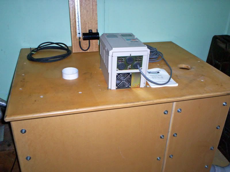
My bench has two test holes, the one on the left blows, and has an extension tube projecting above the bench.
In my case this is solidly connected to the blower outlet within the bench. A bi-directional bench could have something similar, with a sealing flange glued to the pipe stub below the bench top. Pressure would tend to seal any leaks under compression, rather than blow things apart under pressure.
My head fixture, or whatever else I am testing, slips over the end of this pipe and is secured with one or more giant heavy duty hose clamps. It does not leak, and it seems to work quite well.
When blow testing, I can fit PVC pipe extensions of any shape or length to reach wherever they need to go. This is quite handy for intercooler cores, intercooler pipework, mufflers, whole exhaust systems, and so on. I have even blow tested things still fitted into the vehicle !
In this picture the PVC pipe does not appear to project very far above the bench top. It is a tight sliding fit into the bench top, and can be pulled out several inches further to give more length onto which things can be more readily joined. Or it can be pushed right down flush with the bench top to make a conventional test hole. All rather convenient and very easy to use.
Also known as the infamous "Warpspeed" on some other Forums.
- Tony
- Posts: 824
- Joined: Sat Dec 03, 2005 12:34 pm
- Location: Melbourne, Australia
![]() by Thomas Vaught » Thu May 31, 2007 7:28 pm
by Thomas Vaught » Thu May 31, 2007 7:28 pm
I made a testing fixture using a engine block.
I cleaned the engine block well in an degrease/oven type
cooker that removed all of the grease by either stripping it off or burning it off.
I used fibreglas resin and matting to seal off the valley section of the block.
I used a factory metal pan and timing cover with factory gaskets at both locations with a light skin coat of rtv.
I made a pair of plexiglas plugs that would seal the openings where the crankshaft would come out of the timing cover and the rear area of the block.
The oil pan dip stick hole was threaded and a vacuum tap
was installed to read depression across the cylinder heads/ intake manifold/carb.
A bit of work but no leaks, and I can test the entire induction system one cylinder at a time or any combination of cylinders for air distribution.
This is similar to what Smokey Yunick did many years ago.
I can also do exhaust testing as a system by reversing the
flow thru the engine and pulling from a customer supplied race header.
Tom V.
ps Reher/ Morrison/ and Shepard many years ago made a 4 Bore block type deal similar to your set-up but I believe that Buddy M told me that they furnace brazed the block part to a metal plate and mounted that plate to the bench surface (like a roof to the chamber).
- Thomas Vaught
- Posts: 465
- Joined: Fri Feb 18, 2005 5:36 pm
- Location: Michigan
![]() by Griffin » Fri Jun 01, 2007 2:50 am
by Griffin » Fri Jun 01, 2007 2:50 am
those are some great ideas.
We got our issue figured out tonight. Turns out about 17 CFM worth of the flow at 0 flow actual is "noise" in the system as it suplicated with the flow range deadheaded into a rubber cap. We got the rest all but eliminated by going to a thicker rubber gasket between the bench and our block based test fixture.
We got our issue figured out tonight. Turns out about 17 CFM worth of the flow at 0 flow actual is "noise" in the system as it suplicated with the flow range deadheaded into a rubber cap. We got the rest all but eliminated by going to a thicker rubber gasket between the bench and our block based test fixture.
- Griffin
- Posts: 51
- Joined: Wed May 17, 2006 5:55 pm
- Location: Houston, TX
5 posts
• Page 1 of 1
Who is online
Users browsing this forum: No registered users and 5 guests