
200 CFM Research
![]() by 106-1194218389 » Sat May 03, 2008 9:59 am
by 106-1194218389 » Sat May 03, 2008 9:59 am
The port your are talking about is a high swirl port if I remember the Stude heads from way back. They are similar to the Chevy Vortex heads and for what they were designed were excellent. Low speed, low lift swirl and velocity. What you are trying to accomplish that much swirl has to be diminished. My head has the two channels you are referring to. Now be careful adding the second channel as there is water behind the bowl there. Do you have an old head you can saw up? If so cut it up so you can see the thicknesses. I did raise my roof to slow down velocity also. I ended up raising my roof .200". I had a lot of cast iron though so here again is where you measure twice and cut once. I built a set of 383 Chrysler heads where we raised the intake ports 3/4". Were used a killer Devcon to fill first and the whole top of the port was devcon after we ported. We also filled the floor with Devcon to keep the port volume legal. NHRA let us run them for a couple of years and then said :We don't like that anymore!" But in the two years we ran them never had any problems. Let me clarify that we never used Devcon where water was. You can raise the roof and that will also help lower velocities at the pushrod side of port. Also from what Larry Meaux said is you are trying to get your main choke at the throat of the valve pocket or bowl. The farther up the port towards the intake manifold the choke is the worse it effects performance. I think this makes the bowl/throat act like a venturi.
- 106-1194218389
![]() by 200cfm » Sat May 03, 2008 10:48 pm
by 200cfm » Sat May 03, 2008 10:48 pm
Ok, that one channel design makes sense now. The guide boss is rather thick and it would have to be "channeled" a good 1/4" down to equal the other one. I have a junk head and will study the quide boss thickness. If it will take say 1/8" inch depth second channel it might be what is needed.
I reflowed today with the wall insert repair and have moved up a tad. Odd part is I am getting my best low lift values now. Here's where it is at now.
.100 80.3
.200 105.3
.300 136.8
.400 164.7
.450 173
.500 179.4
.550 179.4
.600 180.6
.650 180.6
.670 181.3
Still seems maxed out after .500 lift. I started to grind some more and got curious/suspicious of the air speeds so I rechecked them and got 335 PRt (middle) around 362 on the turn itself and around 323 over the SSR apex. My pitot is DIY so I wondered if perhaps my static point was to far away from the air impact port on the J Bend. The gap is around 3/8"
So, spent the day making a version 2 pitot and put the static port pretty much on line with the other entry port near the tip of the J bend. This changed everything and the new numbers were shockingly high. So high I thought, this is wrong or something is strange. So I added a second hole to the static port and the readings came down better but still higher than version 1 design. So finally I decided to try a tube in a tube design and settle the mystery. Now this was tuff, especially the J bend and keeping both tubes with passages but finally got version 3 working late this afternoon. The new readings are closer to version 2 with the two holes static port and are higher than the version 1 design.
Anyway, the air readings with version 3 pitot are showing higer PRt and SSR apex. Getting 350 fps in the center of the PRT and 360's on the wall turn itself. The SSR is showing more than test pressure. Came in at 380 plus fps. I tested it both a 12" wc (with formula corrections) and at full 28" wc test depressions. SSR was going to 34" wc on the 28 test.
That's a big swing from the pitot version 1 design that has the static port gap.
So like the man with three watches, it's hard to know the real speed. I think version 3 pitot is more on target. Just hard to believe it could be moving that fast. Tubing is bigger on this version, could that be fooling the port CSA and falsing a fps reading?
Now if the air is indeed that fast, my strategy has to be what, slow it down or accept it? I am stuck with factory dual plane iron intakes so should that addition be factored in. The intake will kill a good 12-16 % of the cfm from earlier testings. That kills air speed too, right? Or do you forget about intakes and think head ports only?
- 200cfm
- Posts: 302
- Joined: Fri Nov 17, 2006 10:52 pm
- Location: Virginia
![]() by 106-1194218389 » Sun May 04, 2008 12:58 am
by 106-1194218389 » Sun May 04, 2008 12:58 am
are you making your pitot with one tube insid the other? I think that is what I gathered. Mine I built is 1/16" brass tube inside of 1/8" brass tube. I built a jig to center one tube inside the other so I could solder it in place. Once I had that done and then get the fitting on the end where the clear tubing hooks to segregate the inner tube from the outer tube so I had the two seperate readings then I bent the pitot tube. I devise a neat little mandrel bender to do that. Then I had the one hole in the very end of the bent end to reak pressure and then I put four hole raially around the side of the outer tube a certain percentage back from the tip. I found this at a web site on pitot tubes. If I can find it again I will post the link.
- 106-1194218389
![]() by 106-1194218389 » Sun May 04, 2008 1:51 am
by 106-1194218389 » Sun May 04, 2008 1:51 am
I found this at one web site from a guy that works at NASA:
"A proper pitot tube is a small probe with an elliptical nose that measures total pressure through the center tube and static pressure in the outer duct. Each pressure is usually fed to opposite sides of a manometer. The static pressure enters four or more flush orifices on the outer duct surface. This of course requires some careful machining. A much simpler device could be constructed by building one tube with a hole in the nose to accept the ram (total) pressure and a second to accept the static pressure using surface orifices. Each need an elliptical nose to minimize flow separation. Now, however, they have to be separated a little to prevent flow interaction, and the pressures are not measured at the same place in the flow. This could lead to errors, but if the flow is uniform, say upstream of the test wing, the error should be small."
I looked at Dwyer pitot tubes and they have 8 holes around the side of the tube - Mine has 4 holes and I think I made them .030" and about 1/2" back from the tip.
- 106-1194218389
![]() by 200cfm » Sun May 04, 2008 10:14 am
by 200cfm » Sun May 04, 2008 10:14 am
Ok, looks like my ver 3 has the static hole to close to the ram hole. Didn't know they required some separation. But I assume the two ports (static and ram) have to be centered on the same plane, correct? My first version offered the distance but the ports were not on the same plane. The last version has them on the same plane but also very close with little separation distance. Will study this some more and look into a ver 4. Have you got a close up photo? May have to order one of Bruce's probes to insure the readings are correct. Thanks for the guidance on this.
- 200cfm
- Posts: 302
- Joined: Fri Nov 17, 2006 10:52 pm
- Location: Virginia
![]() by 115-1172523331 » Sun May 04, 2008 11:42 am
by 115-1172523331 » Sun May 04, 2008 11:42 am
Hi Guys, I have been following this thread with great interest because I have been learning quite a bit! In a pitot tube flow element (measuring static and ram pressures), Bruce recommends the static pickup be 1/2 inch before the pitot. Is there any reason that the same wouldn't apply to a pressure probe?
John, the quote you posted sounds like 2 J-tubes with the ram in one and the static in the other. "Each need an elliptical nose...." Is that how you read it? Any pics or the web site available? I have a small port (about 1 in ID) and have been thinking about 2 tubes made of aluminum each 1/16 OD and superglued together but I wasn't going to bend the static tube, just seal it after it passes the ram port. I plan on putting the static openings (probably 3 because one side is against the ram tube) about 1/2 inch before the ram. Even with the tight radius version that Bruce makes, I can't reach the middle of my port as I go past it. I have been able to get to 3/8 radius bend with the small aluminum. My main concern is the the assembly will flail around like grass in a windstorm.
Keep posting your work! -- Doug
- 115-1172523331
![]() by 106-1194218389 » Sun May 04, 2008 12:03 pm
by 106-1194218389 » Sun May 04, 2008 12:03 pm
Here is a picture of one I found on the internet, you will notice that their staticc holes are quite far from the pressure hole in the end. Mine are not nearly this far. I can not find my info I had or where I found it but it gave a percentage to be away from the pressure hole and that is what I went on. I will measure mine later today and see if I can figure out the relationship. I figure measuring air speed on an airplane wing is a little different than what we at doing and iff the static holes are too far away we may not get a correct reading, same if they are too close. Also doing the bend was one of the hardest parts of building my pitot and the tighter the bend the harder. btw I agree with Bruce, 1/2" sounds about right for the static hole distance from the pressure end. I just measure mine and mine are .570". I feel bruce's .500" would be better becasue of the nature of measuring velocity in a port and the SSR and other bends and curves.
- 106-1194218389
![]() by 115-1172523331 » Sun May 04, 2008 12:30 pm
by 115-1172523331 » Sun May 04, 2008 12:30 pm
Hi John, I was just looking at the Dwyer site and found their Series 160 pitot tubes have the static holes 2-1/2 in behind the ram port in a 5/16 OD tube. Their model 167 uses a 1/8 OD tube and positions the static ports 1/2 in behind the tip. I have attached a pic of the latter. -- Doug
- 115-1172523331
![]() by 200cfm » Sun May 04, 2008 12:32 pm
by 200cfm » Sun May 04, 2008 12:32 pm
Wow, that's a nice item. And what a gap distance. Now on the distance issue, I am leaning toward closer. The reason: Say you are measuring SSR apex. If you go 1/2" back on the static the sensing is going to be depression in the bowl itself, almost to the valve stem in my case. To me that would introduce error. Same with say a PRt. I use a trojan mount to steady and peak the readings. A few mm's and you are off the peak, so depth distance or side ways movement is rather sensitive. If the static is much further back behind the ram it is going to be "seeing" a depression way after the turn wall where the port has started its expansion. Maybe my first version is closer after all because the static is on the same vertical plane with the ram. That keeps the depression zone closer to the ram zone. I didn't realize the swing was so much until I built these other two models yesterday. My last design needs more orifice holes. I am at two now but might make a difference if a third is added. Version two started with just one static orfice, then I added a second an it did affect the readings. Looks like an item that needs a reference standard with calibration. Will try an host up a photo of my efforts at pitot engineering.
- 200cfm
- Posts: 302
- Joined: Fri Nov 17, 2006 10:52 pm
- Location: Virginia
![]() by larrycavan » Tue May 06, 2008 8:34 am
by larrycavan » Tue May 06, 2008 8:34 am
That's a good link for anyone who's starting down the road of porting heads. It makes all the different terms used in discussions very easy to understand as well.
Consider this if you will. Some of the big guns have stated that a zero swirl environment is a good thing for high performance. [swirl....not tumble]
On some of the older 2V air cooled motorcycle heads I do, if the runner isn't opened up on the narrow side, the flow can't be had for any amount of effort. It's worth considerable CFM in certain situations. Those are hemi heads though so it's a bit of a different situation than you wedge head guys may run into.
From the factory those heads have bias and swirl built in. It's very easy to spot the fact the factory wanted to aim the charge off to one side of the exhast valve and swirl the air in a spiral around the bores.
Any reshaping of the bowl, regardless of any reshaping on either side of the guide [adding / modifying bias] will completely change the final distribution pattern as the air makes it's final approach to and through the valve area.
So......with that thought in mind, before you decide to alter the bowl shape or fiddle with the bias, maybe take a good hard look at the last flow aiming /shaping possibility you have to work with. That being the shape of the walls in the bowl area.
I believe there are times when a final distribution pattern can become more important that another 10CFM.......
JMO
Larry C
Edited By larrycavan on 1210078648
- larrycavan
- Site Admin
- Posts: 1183
- Joined: Fri Apr 01, 2005 4:40 pm
![]() by 200cfm » Thu May 08, 2008 10:06 am
by 200cfm » Thu May 08, 2008 10:06 am
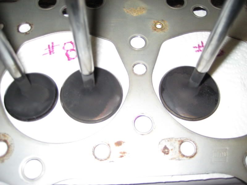
That was a good read article, thanks. Thinking of leaving the single channel design now since swirl helps torque and this is a low rpm pull range engine. The winter project heads on the car now are working fine based on the track runs and they are single channel with bias swirl toward the spark plug it seems. Here is a photo of the valves from the current heads on the bench. I think I see swirl or fuel wash lines.
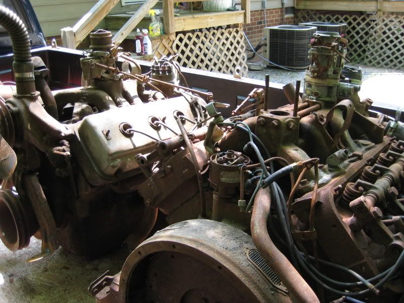
Interesting you mentioned hemi chambers. I got off on a wild tangent Monday and picked up two hemi boat anchors.
Bet these heads would offer 200 cfm.
Interesting you mentioned hemi chambers. I got off on a wild tangent Monday and picked up two hemi boat anchors.
Bet these heads would offer 200 cfm.
- 200cfm
- Posts: 302
- Joined: Fri Nov 17, 2006 10:52 pm
- Location: Virginia
![]() by 200cfm » Sun Jun 29, 2008 10:46 pm
by 200cfm » Sun Jun 29, 2008 10:46 pm
Been so busy racing and fixing the house, haven't had time for flow experiments. BUT, I have an unusual situation. I have started flow test a manifold that I would like to get to work on my engine. It is not a stude manifold.
Today, after setting the head port base line for a reference using only the port radius attachment. I get an increase in cfm at all lifts when the manifold is attached to the head. I have never seen this before. Is this even possible? I have checked it twice and it did the same. Flow increases over the base radius plate cfm numbers at all lift points when the intake manifold is attached. Manifold port runner under test is number 3. Number 1 had a % cfm loss but not as much as the factory studes dual plane intake which is the goal of the project.
I keep thinking my bench is acting up or I am doing something wrong or ?. Is it possible for the port to increase over the base line when the manifold is attached? Anyone ever seen this behavior? Thanks.
- 200cfm
- Posts: 302
- Joined: Fri Nov 17, 2006 10:52 pm
- Location: Virginia
![]() by larrycavan » Sun Jun 29, 2008 11:02 pm
by larrycavan » Sun Jun 29, 2008 11:02 pm
Things can fall into place where that can happen.
That's really funny how you question your bench. I had that happen to me on more than one occasion. I keep a quick check plate handy for those situations. One that I have flowed on my test stand on a SF bench and then verified on my bench. It's quick to use and take the guess work out of the calibration in a hurry.
Just make sure the manifold isn't rocking the head off it's seal or something like that. Hope it turns out that it's improved for real for you.
- larrycavan
- Site Admin
- Posts: 1183
- Joined: Fri Apr 01, 2005 4:40 pm
Who is online
Users browsing this forum: No registered users and 3 guests