
Race season has ended so in the coming weeks/months I will have time to research a test head. Started yesterday for a base line. Fired up my Turbo 200 bench, slapped on a standard stude head with generous clean up only and got 133.4 cfm at 28" wc @ .400" Made a pitot check at mid point on the pushrod pinch area and got around 19" rise which converted to 288.5 fps. Valve size is 1.656." And valve seat angle is 45 degrees. I am told these heads have a 12 degree valve angle. Have made some molds so can post them up for study if anyone is interested.
Next up, I removed the intake valve. Reflowed and got a max of 180.1 cfm. Made a pitot check at same point and notice very high pitot pressures especially as I moved over closer to the pushrod pinch wall. Much lower pressures approaching the other wall. Saw as much as 40" wc which converted over to 418.6 fps.
More data gathering to follow. That's all I have learned so far. What's the best approach study plan if this were your port?
200 CFM Research
![]() by 86rocco1 » Fri Dec 14, 2007 1:14 pm
by 86rocco1 » Fri Dec 14, 2007 1:14 pm
I don't have anything to contribute but I'm going to give this thread a bump because I'd like to see it turn into a discussion of how to use a flowbench to good effect and to that end, I think your situation would make an interesting case study.
- 86rocco1
- Posts: 292
- Joined: Sun Nov 18, 2007 5:46 pm
![]() by 200cfm » Sat Dec 15, 2007 12:16 am
by 200cfm » Sat Dec 15, 2007 12:16 am
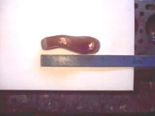
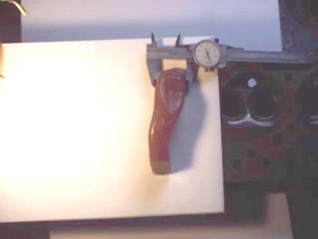
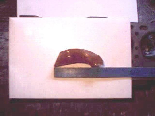
Thanks, here are some photo views of a standard port. When I first got the bench humming this spring I worked some on another set of heads that already had larger valves (1.870)and a 3 angle valve work. I flowed it and got a base and made modest changes and measured some gains. But didn't change much because wasn't sure of the steps and race season was starting and needed the heads on the motor.
- 200cfm
- Posts: 302
- Joined: Fri Nov 17, 2006 10:52 pm
- Location: Virginia
![]() by gofaster » Sun Dec 16, 2007 4:22 am
by gofaster » Sun Dec 16, 2007 4:22 am
Once you cut your three angle valve job into the seat for the larger valve, blend the bowl right up to the 60 degree cut. When you're done blending the bowl, the 60 degree cut should be about as wide as the 45 degree cut.
The side view of your port mold shows a generous shortside radius and a fairly high floor. That's a good thing. I wouldn't remove any more material from the floor or shortside beyond what is needed to make it smooth.
The top shows a heavy guide boss. I would teardrop the boss nice and rounded, and radius cut the top corners into the roof as high as it's safe to go, with a gentle blend to the top/back of the bowl.
Then I would bring the four corner radii out to the mouth of the port, working from inside to the mouth. I would make the corners as large a radius as is practical without getting into the pushrod openings, waterjackets, etc.
After that I would work to flatten the walls to match the corners, and in doing so, try to take advantage of the most material possible in the pinch area to attempt to straighten that part out a little bit to reduce the local high velocity.
The wall opposite the pinch may benefit from some epoxy to flatten the outside of the dogleg. I like trying epoxy, because it's no problem to carbide it back out if the results don't pan out.
Jim
- gofaster
- Posts: 237
- Joined: Fri Jul 01, 2005 6:39 pm
- Location: Indiana
![]() by 200cfm » Mon Dec 17, 2007 11:16 am
by 200cfm » Mon Dec 17, 2007 11:16 am
Thanks Jim for the recommendations. Nothing like a guiding light as you enter into an unknown room. I am waiting for Pipemax 4.0 to be introduced to gain understanding on where to put the CSA and lengths. And taking notes on an approach strategy.
- 200cfm
- Posts: 302
- Joined: Fri Nov 17, 2006 10:52 pm
- Location: Virginia
![]() by larrycavan » Tue Dec 18, 2007 8:15 pm
by larrycavan » Tue Dec 18, 2007 8:15 pm
Don't worry about what the velocity is with the valve out of the port. 288 with the valve in is good.
You don't have to wait for ver 4. Get the current version. Larry has always released upgrades for free in the past. Give him a shout to verify that's still the case.
Do you not have any formulas to work with for now? Holler if you need them.. In fact, if you want, you give me the input criteria for your motor that PipeMax needs and I'll run it through and post it for you. You can visit Larry's site to get a screen shot of PM so you know what the inputs are.
Happy Holidays,
Larry C
- larrycavan
- Site Admin
- Posts: 1183
- Joined: Fri Apr 01, 2005 4:40 pm
![]() by larrycavan » Tue Dec 18, 2007 8:18 pm
by larrycavan » Tue Dec 18, 2007 8:18 pm
- larrycavan
- Site Admin
- Posts: 1183
- Joined: Fri Apr 01, 2005 4:40 pm
![]() by 200cfm » Tue Dec 18, 2007 11:43 pm
by 200cfm » Tue Dec 18, 2007 11:43 pm
I have a few formulas thanks to the forum and Speedtalk. Made a measurement of the roof and floor mold. Roof is 14.5 cm and floor is 11.0 cm. Adding the two together nets 25.5 cm and dividing by 2 to get the centerline average nets 12.75 cm. Then converting by 2.54 cm/inch nets an average centerline port length of 5.0 inches.
Haven't measured the manifold runner yet.
Tomorrow I will try and measure the cc volume of the intake port. I have Pipemax 3.6 version. Is that ok for boosted engines?
Haven't measured the manifold runner yet.
Tomorrow I will try and measure the cc volume of the intake port. I have Pipemax 3.6 version. Is that ok for boosted engines?
- 200cfm
- Posts: 302
- Joined: Fri Nov 17, 2006 10:52 pm
- Location: Virginia
![]() by 86rocco1 » Wed Dec 19, 2007 12:26 am
by 86rocco1 » Wed Dec 19, 2007 12:26 am
Thanks Larry.
Math is what I'm good at. I firmly believe that if one understands the basic math involved with flowbench operations that goes a VERY long way to understanding how to design and build a flowbench. My spreadsheets were designed to help people get a handle on that and I'm very gratified to know that my work is having the desired effect.
Math is what I'm good at. I firmly believe that if one understands the basic math involved with flowbench operations that goes a VERY long way to understanding how to design and build a flowbench. My spreadsheets were designed to help people get a handle on that and I'm very gratified to know that my work is having the desired effect.
- 86rocco1
- Posts: 292
- Joined: Sun Nov 18, 2007 5:46 pm
![]() by 200cfm » Wed Dec 19, 2007 11:03 pm
by 200cfm » Wed Dec 19, 2007 11:03 pm
Measured a port volume today. Didn't have a pro burette so used a liquid dropper. Actually used two styles (one a 5ml and the other a 10 ml). Tested volume twice using each dropper and came out 137 and 138 ml. So I split the average for 137.5 cc. port volume. To find the average CSA I used the formula: CSA avg = (Port Volume cc divided by Port Length) and that value divided again by 16.387.
Sooo, 137.5 cc / 5.0 = 27.5 / 16.387 = 1.678 sq. inch.
Summary: Average Port CSA = 1.678 sq. inch
Port Volume = 137.5
Then I flowed some valve lifts to refresh the procedure and the math. Calculations came out:
Lift .100 .200 .300 .400
CFM 55.3 92.7 116.8 137.2
Example: on an incline rise of 45 cm and a total length of 76.2 incline you get 45/76.2 = .59055. Taking the square root of this value nets .7685 which is also the 76.8 % flow mark on the incline. 76.8% flow of the selected orifice plate (178.6 cfm) nets 137.2 cfm @ .400 lift @ 28" wc.
Although my incline is marked in % flow I always use the math to insure better accuracy. Then for a "What If Test" I removed the 1.656 valve and installed a smaller sbc 1.500 exhaust valve just to see what it flowed. I was expecting an increase because of less chamber shrouding. Well it was down 3-4 cfm on all lifts. That surprised my theory thinking and so I pondered why and concluded it must be because of the thick tulip section behind the valve on the 1.500. I think the thicker mass area where the stem connected to the valve was reducing the curtain area and reducing the throat area. Only explanation I could come up with. Despite the cold it was a good day with the water manometers.
- 200cfm
- Posts: 302
- Joined: Fri Nov 17, 2006 10:52 pm
- Location: Virginia
![]() by 200cfm » Sat Dec 22, 2007 12:31 pm
by 200cfm » Sat Dec 22, 2007 12:31 pm
[color=#000000]Spent several hours this week reviewing all my forum notes and printouts on air speed theory. Pulled a head off an engine I had race earlier last spring. This head had been reworked way back in the early 80's. A machinist put in a larger valve for me and I opened up the ports, bowls. My work was more of a bigger must be better effort at that time using stones and hand grinding. But I never had any bench data on the heads Just some time slips. In my race Lark at 3090 lbs these heads had gone an average of 12.80's at 105 -106 mph range behind 10 lbs boost. on a 298 block (that's 289 plus .060 bore.) Soo with a forum design bench I was very curious as to where the flow and air speeds might be. Hoping to use the data to gain insight on how a port should be shaped, etc. So here is the data on these heads as collected yesterday.
Lift: CFM
.100 64.7
.200 110.2
.300 144
.350 XXX
.400 170.6
.450 XXX
.490 182.6
.550 XXX
.590 194
The time slip data is based on a cam that peaks .400 max lift.
But I took higher lift measurements for a future roller cam reference. The intake valve is 1.780". Actually an old Pontiac TRW valve that the machinist cut back. There is only one valve seat at 45
- 200cfm
- Posts: 302
- Joined: Fri Nov 17, 2006 10:52 pm
- Location: Virginia
![]() by 106-1194218389 » Sat Dec 22, 2007 8:45 pm
by 106-1194218389 » Sat Dec 22, 2007 8:45 pm
I have a question for everyone. He mentions 10 lb boost. How much do you need to pay attention to velocity if you are running a supercharger or turbo? I have a friend who is running a little Honda with a ton of boost. His little car runs 9.40's at 149 mph. The ports look bigger than my small block chev. Seems to work. I personally have not played with heads for a boosted engine. Wouldn't you do the heads different than a naturally aspirated engine?
- 106-1194218389
![]() by 200cfm » Sat Dec 22, 2007 10:01 pm
by 200cfm » Sat Dec 22, 2007 10:01 pm
Good question and I don't know off hand John. I do know that if the heads don't flow good the boost will back up giving you high boost readings from the back up. Good heads sink the air into the engine is my thinking. You really want to sink as much of the boost pressure as possible. 10 lbs is a lot of pressure and indicates head flow back up to me. I have another set of heads on a 298 motor that I hope to pull later this winter. Those heads I reworked years ago too and they are the my best et and mph heads on the same displacement/cam motor combo. Those heads have gone a best of 10.98 at 120 plus in the new 08 pro chassis car I am still preparing. It weighs less (2630) but the only difference in the two motors are the heads. Why do they work so well? The valves are bigger (1.840") which helps but the ports are truly hogged out. It's a wonder I didn't hit water. Years ago I opened them up using a early Cadillac intake template gasket. The idea was to use a 57 Cadi intake on the heads. Never got around to the Cadi intake. Engine ran so well with the factory intake I just stayed with what worked. But the much larger ports in these heads agree with your Honda observation. So may bigger is better on boosted engines. I am eager to flow them and map them.
I have always thought that boost increases air speed in the port. People more knowledgeable than I state it can only increase air density and not speed. I understand the density increase but still picture in my head much higher port air speeds exploding through the valves, etc.
Anyway I spent some time this evening making a "what if" change on the above port. I concluded from the port mapping that the pushrod turn was to narrow and needed widening and a longer radius. So for an hour I hand filed it down carefully reducing the apex of the turn from top to bottom. Put it on the bench before dark and got the following profile.
Pushrod Turn @ .350" lift (78% rule)
21/303 20.5/300 20/296
20/296 20/296 19/289
19/289 18/280 18/280
SSR apex 20/296
SSR rollover 21/303
I immediately notice a decrease in speed in all areas and much better balance of pressures in the section. I thought this would change the SSR values but they stayed about the same. And I recheck the cfm at .400 and .300 lift and they stayed the same too. So I didn't see any cfm increase but no significant losses either. About the same. But
When I put the string tester back in I had a very pleasant surprise. The floor was steady and straight but as I lifted the string it flowed straigher for a much higher rise off the floor. In fact it didn't start to swirl around until I got close to the mid section or almost half way off the floor. The swirl still exists on upwards toward the roof but less overall. So I am thinking this is a plus for the port.
And I took a measurement on the throat diameter. It is coming in at 1.535". That gives a 86% throat to valve ratio which I am thinking now may be too small. A small throat would make the SSR go faster right? Maybe I should open it up gradually and see what it nets.
That's all I have had time to discover this week. Merry Christmas to All!
- 200cfm
- Posts: 302
- Joined: Fri Nov 17, 2006 10:52 pm
- Location: Virginia
![]() by 200cfm » Sun Dec 23, 2007 11:11 pm
by 200cfm » Sun Dec 23, 2007 11:11 pm
Today I made some needed improvements on controlling certain measurements on the bench. Just wasn't happy with the system of opening the valves so (1) I redesigned the lift feature. Instead of placing the dial indicator leg on the retainer I moved it to the stem itself. Then put together a simple standoff to make adjustments that move the retainer instead of the earlier version which moved the stem directly. In other words I reversed the tasks. Now the indicator returns dead on zero start reference everytime. Before it would sometimes shift a few thousandths due to referencing from the retainer. And I added a dual spring instead of a single standoff spring under the retainer to increase tension on the whole retainer. Then to increase accuracy again i decided to actually measure the angle of the dial indicator so that it would be in agreement with the valve stem. Used a simple 360 degree gravity degree scaler to adjust the dial indicator to 12 degrees. Measurement is made off the face of the indiator because that is the level part. Just place the angle finder lightly up against the face of the dial indicator and adust. Once the angle is set the vertical portion of the indicator leg can be "eyed" very closely by imaging a plum line behind the indicator at 1200 and 1800 hours. This should reduce any cos sine angle shifting as the indicator drops down. I was concerned that by .500 plus lift the shift might be adding up a few thousandths.
Next up was a better method to make pitot measurements up inside the port. The time I spent trying to get a pitot profile the other day was difficult and I kept thinking there has to be a better method. So what I came up with was a simple moveable stand to hold the pitot tube at various depth or height inside the port. I surnamed it: Pitot Trojan Horse Mount. I selected 1/4 inch thick steel bar base 2X4 and welded up a 1/8 by 2X6" bar to the sides of the thicher bar base. Then drilled a hole through the flat bar for a clamping bolt that clamps a second shorter 1/16 X 1 X 2 bar that clamps the pitot tube. T handle 1/4" bolt allows simple tension control to clamp the pitot or shift it around for different heights up inside the port.
The heavy metal used keeps it from tilting over and offers fixation by weight. Now I can slide the pitot up into the port, fix the portion to be measured, and fire up the bench. Once the test pressure is set you can make small hand control in/out, up/down movements of the mount and find the very peak or dip of the section in the port under investigation.
One final tip that I discovered. I got tired of holding a flashlight up inside the port and hand shaking the pitot. So the mount solved the handshaking and a big high beam light solved the port darkness problem. I opened up the marine deck port hole and installed a high intensity battery operated lamp under the bench cylinder hole. This light has one of those car size bulbs in it and it will through a light across a foot ball field. I cut it on and boy can I see the port now. It views so well, I can make far better pitot placements around the bowl to throat to valve areas. Hope you can benefit from this. Now time to play Santa. !
- 200cfm
- Posts: 302
- Joined: Fri Nov 17, 2006 10:52 pm
- Location: Virginia
Who is online
Users browsing this forum: No registered users and 2 guests