
hello,
i have a bit of a silly question. If you have an annubar type bench, do you have to have two of them in the flow stream in order to flow intake and exhaust, one facing each direction?The other question I have is, what inside diameter or o.d. do you have to have to support, say, 550cfm at 28"?
thanks,
shawn
silly ?
12 posts
• Page 1 of 1
![]() by 98-1074649673 » Sat Apr 24, 2004 7:52 am
by 98-1074649673 » Sat Apr 24, 2004 7:52 am
Originally I had 2 annubars facing different directions. I now flow the air the same direction through my bench and draw the air out of the exhaust port into my bench with a tube or connection of some type. This way I do not have to worry about the heat generated by my blower. Seems to work for me. There are other design ideas on the forum that address this problem that might fit your needs better?
550cfm @ 28" whatca testing?
550cfm @ 28" whatca testing?
- 98-1074649673
![]() by Shawn » Sat Apr 24, 2004 1:33 pm
by Shawn » Sat Apr 24, 2004 1:33 pm
I have ported everything from a kart head to pro-stock style big cheif heads. A good oval port big head will go about 525cfm @28"'.I use a SF600 now but want something that i can create large depression with. In the area of 38"-44" for flowing exhaust ports.( Some different idea's that i'm working with).I don't want to spend the money to have a custom bench built, when i know that i can do it myself for much less.I think that the annubar or pitot tube style is what i have settled on for design. I know that Dart heads just built one to do something very simillar to what i'm wanting to do, and they used a pitot tube from dwyer.If i use two annubars,what distance do they have to be away from each other, not to upset the flow?I know that in a 3" PVC, most people seem to agree that about 10 times the diameter is what you want for straight pipe length. I would think that the same distance between the two should be enough, what do you think? My preliminary idea is to have a flow straightner, 30" of pipe, annubar,another straightner about 10" behind it,10" of pipe, annubar,30" of pipe, another straightner.Audie tech sells these really neat honeycomb air straightners for next to nothing.The two "sections" would be parallel to each other, so i wouldn't have a bench that was 80"+ wide.This forum is great. I'm glad that i have some people to bounch these ideas off of. Hope that i can try to contribute something. I'll make sure to take pics and post them as my project developes.
thanks again,
shawn
thanks again,
shawn
- Shawn
- Posts: 71
- Joined: Thu Apr 22, 2004 12:47 pm
![]() by bnelson » Mon Apr 26, 2004 9:26 pm
by bnelson » Mon Apr 26, 2004 9:26 pm
Shawn,
I work as an industrial piping designer......and the stuff I do usually figures anywhere from 20diam up and 10diam down to less at 10diam up and 5 diam down. This doesn't take into account what is at the end of the straight run, like a 90 deg elbow, tee, valve etc. It is also good practice to try and keep all the changes of direction in the same plane if you can, otherwise you need to add extra straight run. I have some charts at work that show a bunch of different options with the different recommended straight runs required. Alot of it depends on the device and what the manufacturer recommends. I have the meriam anubar catalog infront of me as I type this and it has a table with different recommendations based on the configuration. I'm a bit confused by your description........cause it sounded like you were proposing to use one straight pipe with 2 anubars both facing opposite directions (assuming flow in both directions depending on what kind of test your doing) then at the end you say they will lie parallel to each other?? If you are going to have 2 "meter runs" (what we call them in the business) parallel to each other and connected together on one end don't use a 180 degree bend. You must use 2-90's connected by a straight piece of pipe with no less than 10 diameters between them. Flow straightners will help reduce some of the straight run required. Remember each change of direction, fitting, length of pipe change in diameter or straightener adds pressure drop..........so in other words a straight piece of pipe with no bends has the least amount of loss......most the time a few fittings etc aren't enough to create enough drop to get you into trouble......but a good design will try to minimize the pressure loss.
I work as an industrial piping designer......and the stuff I do usually figures anywhere from 20diam up and 10diam down to less at 10diam up and 5 diam down. This doesn't take into account what is at the end of the straight run, like a 90 deg elbow, tee, valve etc. It is also good practice to try and keep all the changes of direction in the same plane if you can, otherwise you need to add extra straight run. I have some charts at work that show a bunch of different options with the different recommended straight runs required. Alot of it depends on the device and what the manufacturer recommends. I have the meriam anubar catalog infront of me as I type this and it has a table with different recommendations based on the configuration. I'm a bit confused by your description........cause it sounded like you were proposing to use one straight pipe with 2 anubars both facing opposite directions (assuming flow in both directions depending on what kind of test your doing) then at the end you say they will lie parallel to each other?? If you are going to have 2 "meter runs" (what we call them in the business) parallel to each other and connected together on one end don't use a 180 degree bend. You must use 2-90's connected by a straight piece of pipe with no less than 10 diameters between them. Flow straightners will help reduce some of the straight run required. Remember each change of direction, fitting, length of pipe change in diameter or straightener adds pressure drop..........so in other words a straight piece of pipe with no bends has the least amount of loss......most the time a few fittings etc aren't enough to create enough drop to get you into trouble......but a good design will try to minimize the pressure loss.
- bnelson
- Posts: 25
- Joined: Thu Apr 08, 2004 11:35 pm
![]() by Shawn » Tue Apr 27, 2004 9:20 pm
by Shawn » Tue Apr 27, 2004 9:20 pm
hello,
thanks for the input.Thanks also for the reply to my email from TOO's board. I have changed direction a little bit, going to a pitot tube style bench vs. a LFE.I have some plans drawn up. If I can find a way, i'll post them here, or email them to you for your opinion.
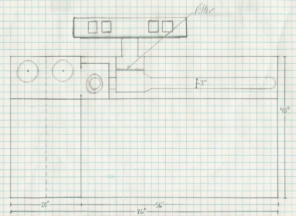
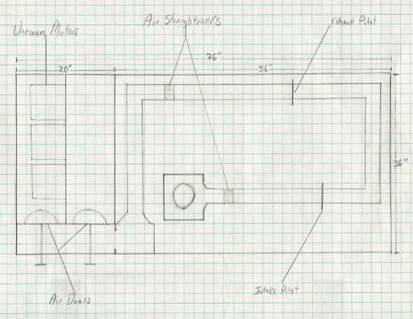
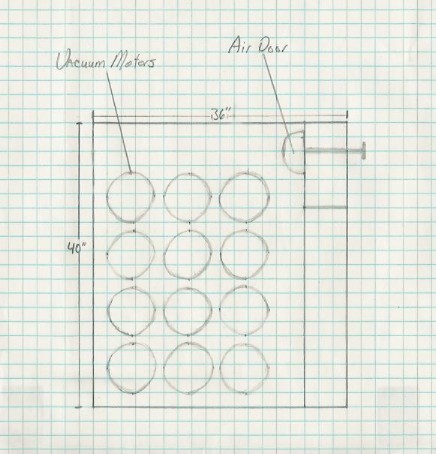
I plan on having a chamber with the motors and two air control valves.One to open for intake flow, the other for exhaust, that's why the two annubars. One for each direction of flow.I didn't want one to affect the reading of the other, that's why the two parallel "meter runs".My idea, if i can explain it, is to drop vertically from the left front side of the bench, into a 90* bend, run horizontally from there for whatever desired length needed to place the annubar in this run, and 90* bend sending it toward the back of the bench, ( i have about 20" of room to do this),into a 90* bend to send it back on a long run to the left end of the bench. This is where i would place the other annubar.This run would end in a 90* vertical bend to the top of the vaccum chamber.I have re-thought the amount of air director's and i'm going to just settle for two, about 25" up stream of each annubar, in relation to the travel of the air, of course.
Another question I have is about a "settling" chamber just under the deck of the bench. Is this required, or recommended?If so what should it look like? A "V" shaped box or maybe just a large diameter tube?(maybe 10"-12")?
hope this makes sense,
Shawn
thanks for the input.Thanks also for the reply to my email from TOO's board. I have changed direction a little bit, going to a pitot tube style bench vs. a LFE.I have some plans drawn up. If I can find a way, i'll post them here, or email them to you for your opinion.
I plan on having a chamber with the motors and two air control valves.One to open for intake flow, the other for exhaust, that's why the two annubars. One for each direction of flow.I didn't want one to affect the reading of the other, that's why the two parallel "meter runs".My idea, if i can explain it, is to drop vertically from the left front side of the bench, into a 90* bend, run horizontally from there for whatever desired length needed to place the annubar in this run, and 90* bend sending it toward the back of the bench, ( i have about 20" of room to do this),into a 90* bend to send it back on a long run to the left end of the bench. This is where i would place the other annubar.This run would end in a 90* vertical bend to the top of the vaccum chamber.I have re-thought the amount of air director's and i'm going to just settle for two, about 25" up stream of each annubar, in relation to the travel of the air, of course.
Another question I have is about a "settling" chamber just under the deck of the bench. Is this required, or recommended?If so what should it look like? A "V" shaped box or maybe just a large diameter tube?(maybe 10"-12")?
hope this makes sense,
Shawn
- Shawn
- Posts: 71
- Joined: Thu Apr 22, 2004 12:47 pm
![]() by 98-1074649673 » Tue Apr 27, 2004 10:02 pm
by 98-1074649673 » Tue Apr 27, 2004 10:02 pm
My current bench has a small settling chamber for me to take my static pressure reading from for my test depression. My new bench I am building has a much larger settling chamber that is 6" dia and about 16" long. This necks down to a 4" -3" 90* elbow at the end of this elbow will be the location of my flow straighteners (on my current bench this is nothing more than a peice of 3" PVC filled with soda or as others call them pop straws they are all hot glued together) my new bench will have honeycomb in this location instead. from here its on to my flow elements (these will be removable, currently I just disconnect the PVC pipe I have slipped together) They are made in various diameters based on what I am testing, 3", 2" 1.5". Sorry don't have an idea of what dia does what CFM yet that will all depend on my final blower selection (did I say final? Are our flowbenches ever finalized?) After the flow element I have a 3" slide gate valve that controls my airflow. My idea was to keep it simple, seems to work for me and is very repeatable in operation. I do all my flow testing in one direction. I don't like the idea of heating up the air blowing back through the bench.
- 98-1074649673
![]() by 98-1074649673 » Fri Apr 30, 2004 9:16 pm
by 98-1074649673 » Fri Apr 30, 2004 9:16 pm
The annubars have one set of holes drilled into the face so you need a set of 2 if you are reversing flow direction in your bench.
A word about what I supply as "annubars" they are nothing more than a peice of 1/8" brass tubing with one set of precision holes located on the face at exact locations based on an airflow industry standard location for duct traversing.
If you look up duct traversing on the net you can find this information. I have found they work quite well and have refined my design over the past few years to what I use on my bench. Probably not up to industry standard for airflow testing to ISO9000 or ASHRAE but they work and thats what matters.
Sure can't beat them for the price if you are the DIY'er thats for sure . . .
- 98-1074649673
![]() by 84-1074663779 » Sat May 01, 2004 6:51 pm
by 84-1074663779 » Sat May 01, 2004 6:51 pm
Shawn, I have never built a pitot bench, so this is all speculation.
The idea of having a ninety degree pipe bend before the measurement run worries me, because some flow disruption and turbulence around the bend is inevitable. A flow straightener immediately after the bend might work quite well, but I have never tried it.
Another way might be to have a large plenum space directly below your suction test hole, and then have a very graceful flared entry into your straight horizontal measurement section.
My thinking is that the plenum will reduce the air velocity and allow it to lose a lot of turbulent energy. The air can then get a straight shot down the measurement section. This works very well in my orifice bench, and should work just as well if the orifice was replaced with a long pipe and pitot measurement system.
The bench top test hole and flared pipe entry should be out of direct line and as far apart as possible.
Another thing to think about is that normal plumbing plastic pipe elbows are made very sharp so the pipe can go around the acute corners you find in buildings. This is going to be far too sharp a change of direction for flowbench pipework.
Large diameter underground electrical conduit (orange) can be purchased that has very large radius smooth bends so you can install massive electrical cables with a pull through, after the conduit has been buried. I believe different radius bends are available. If you simply must have a bend, a smooth large radius is probably going to work better than a very sharp elbow followed by a straight pipe. It will have less pressure drop and that should tell you something.
- 84-1074663779
![]() by 98-1074649673 » Sat May 01, 2004 10:45 pm
by 98-1074649673 » Sat May 01, 2004 10:45 pm
Since I have built and am using a pitot style bench using PVC pipe I'm gonna weigh in on this post again . . .
My 90* pipe coming off my settling chamber under my test peice is a 4" to 3" reducing bend, right after the bend I have installed a flow straightening peice of 3" pvc with an array of soda straws (for us east coast people, pop straws for the rest of the world) hot glued in place this peice is approx 2-3" long (out sourcing some type of honeycomb for this instead). With my annubar setup I have not seen any ill effect on flow readings.
My theory has always been to keep it simple and easy to build, as I've learned with this bench, I've tried new things and will be incorporating them in my new bench thats in the "build" right now. PVC is very easy to work with and I find it works quite well in my application . . . ok enough of me trying to sell my ideas, thats what I like about this forum so many different ideas come out!!
- 98-1074649673
![]() by bnelson » Sun May 02, 2004 1:33 pm
by bnelson » Sun May 02, 2004 1:33 pm
Going on memory from some of the stuff in my Crane book.....I think 2 diameter bends are suppose to be ideal. However, I think this is one of those things where the best series of compromises makes the best bench. I tried to keep mine 1.5 or greater. Some of this I think is splitting hairs. I know I would get caught up in fine points on stuff when, according to the hvac engineers I work with, for what I was doing it didn't really matter. If you try to remember that most the time a bench is just a comparator for before and after checking of a part your modifying........and, as Bruce has said, repeatablity is the key. It can measure qumquats as long as it is repeatable. I went with the mandrel bent exhaust since it is really smooth inside......and the bends weren't the expensive. If I didn't have a welder however, I propably would have used plastic, and possibly conduit bends as mentioned above. I think they are either 3 or 5 diameter bends.
On another subject.......flow straighteners.........while looking for the bend diameter info.......I ran across a formula in a copy of some info out of the Fan Engineering book by Buffalo Forge Co. It says that assuming the straightner has square cells......that the side dimensions of the cells should be 7.5% of the pipe I.D. and the length of the straightner should be 6 times the side dimension of the cell. This straightner is suppose to produce a loss equivalent to 12 diameters.
On another subject.......flow straighteners.........while looking for the bend diameter info.......I ran across a formula in a copy of some info out of the Fan Engineering book by Buffalo Forge Co. It says that assuming the straightner has square cells......that the side dimensions of the cells should be 7.5% of the pipe I.D. and the length of the straightner should be 6 times the side dimension of the cell. This straightner is suppose to produce a loss equivalent to 12 diameters.
- bnelson
- Posts: 25
- Joined: Thu Apr 08, 2004 11:35 pm
![]() by Shawn » Mon May 03, 2004 2:55 pm
by Shawn » Mon May 03, 2004 2:55 pm
Here is some drawings of my bench idea. Keep in mind that all of the 90* bends will be large radius bends, not sharp 90's. I found some info. on pitot tube requirements as far as straight pipe needed. Here they are-
upstream with straight w/0 straight
disturbance vanes vanes[U]
one elbow or tee 6-8 8-10
two 90* bends
in same plane 8-10 12-15
two 90* bends
different plane 10-12 24-28
these are all times inside pipe diameter diameters. Thought you guys might like this info. It comes from Meriam,so the standards upheld are probably alot higher than what we would require.Let me know what you think about my bench idea.
thanks,
Shawn
Edited By bruce on 1083622232
- Shawn
- Posts: 71
- Joined: Thu Apr 22, 2004 12:47 pm
12 posts
• Page 1 of 1
Return to Pitot Style Bench discussion
Who is online
Users browsing this forum: No registered users and 3 guests