
Just though I would take the liberty of resurecting this topic again as it was so very popular.
**************
I have been giving some thought as to how the water supply into this type of home built water brake dyno load could be controlled with a computer interface, without having to buy something horribly expensive to do it.
The requirement is to be able to very rapidly, but also with great precision and sensitivity, open and close a water control valve that can handle both a high water source pressure and also have a sufficiently high water flow capacity.
A commercial stepper controlled valve would not come cheap, and neither would the interface electronics to convert computer commands to the high electrical power required to drive the actual stepper motor.
One possible budget solution may be to use an external turbocharger wastegate to control water flow. Even the smallest sized wastegates will have a sufficient flow path to handle the water flow into the dyno absorber. The low cost diecast body Chinese wastegates would be well up to the job.
Fitted with a suitably stiffer spring, variable air pressure into the control diaphragm could then be used to modulate water flow.
A small low power (automotive type) air solenoid valve could then be pulse width modulated from a very simple computer interface at fairly at low cost.
The way I can visualize this working would be to reduce the shop compressed air supply down through an adjustable pressure regulator to maintain a constant reference supply pressure.
The compressed air then passes through a small flow restriction orifice into the wastegate chamber, and also to the control solenoid that can vent this same flow limited air supply.
With the control solenoid closed, the wastegate will receive full reference air pressure, and will be wide open at 100% water flow. The spring in the wastegate and the reference air supply pressure can both be adjusted so the wastegate opens fully.
With the control solenoid held permanently open the air pressure at the wastegate will be fully vented, and be just about zero. The wastegate will then be fully shut, and water flow will be 0%. The spring in the wastegate will need to be made sufficiently strong to resist the highest expected water source pressure.
If the air pressure control solenoid is pulse with modulated at a reasonably fast rate, and if the air volumes in the control system are kept small, the water control valve can be very rapidly moved and held part open to any required degree.
The whole thing can be made from fairly readily available bits and pieces, and the cost might be acceptably low for a home dyno project.
It is also reasonably fail safe, in that if the mains power suddenly fails, the full stored shop air supply pressure opens the wastegate fully, and floods the dyno applying maximum dyno load.
I have never built or tried this, it is just an idea at this stage.
home made water brake (topic continuation)
21 posts
• Page 1 of 2 • 1, 2
![]() by 74-1167423495 » Wed Jan 03, 2007 8:14 am
by 74-1167423495 » Wed Jan 03, 2007 8:14 am
Hi, Im new to this forums, so hello and Happy new year !
Im very interested in making my own home dyno.
And the waterbrake dyno seems to be the most affordable thing.
I had read the old thread and I have to say that is the very first place for years of seaching that I found any concluyent information.
Im a mechanical designer and according to what I had read I designed a 6" water brake with 11 blades impeller, 12 blades or alternatively blank case, and 1/2" inlet and outlet. It have a hollow shaft that allows a simple ataching to the drive shaft and a series arrangement if the absorbed power isnt sufficient.
Seems to be a simple desing. But there are some questions
What benefit I will obtain with the bladed case? because the blank case is a revolution part that can be obtained by lathe, and the vaned alternative must be machined.
I saw that the stuska impeller have not evenly spaced vanes, but odd spaced, is this a must to obtain a smooth torque?
My dyno will be fairly simple, because my engines are air cooled, so ill will plug the brake to a tap throug a plastic garden valve, and if the thing works, I will attach a servo to it, and automate controll by any mean.
- 74-1167423495
![]() by DaveMcLain » Wed Jan 03, 2007 10:31 am
by DaveMcLain » Wed Jan 03, 2007 10:31 am
I believe the general consensus is that there should be a different number of vanes on the rotor than the case so that the absorber doesn't tend to pulsate. I've not counted the vanes on the case vs rotor on my Land and Sea absorber to see if it's made that way, but I bet it is... Something like a 12 vane rotor and a 13 vane case is what I'm thinking.
A water brake is very simple, can absorb a lot of power for it's size and cost and is easy to control with a simple water valve and drain orifice, I think you'll be surprised at how simple the whole thing is, most people are when they see my dyno in action. Personally I think that the data recording is much more complicated than the actual dyno.
Depending on your design of course I think you'll be able to load about 200 horsepower with a typical garden hose water supply and still have a reasonable outlet water temp.
- DaveMcLain
- Posts: 110
- Joined: Sat Jan 01, 2005 10:30 am
- Location: Cuba MO USA
![]() by Tony » Wed Jan 03, 2007 2:44 pm
by Tony » Wed Jan 03, 2007 2:44 pm
Juan, so very much depends on the power level of your air cooled engine.
A smooth housing is going to offer very little torque load resistance. The water will simply spin around inside at very nearly the same Rpm as the rotor. With a very small capacity, high Rpm engine, that might still work o/k.
With a larger capacity engine where a lot more low speed torque loading is required, there should be similar sized vanes on both rotor and housing. From what I have been able to discover, if the rotor has twelve vanes, the housing should have either eleven, or more likely thirteen vanes.
Both rotor and housing halves could be machined from solid metal blanks, but I plan to sand cast these in aluminium. These castings could then be turned on a lathe to get the required close fits in all the important places.
I have never attempted to cast metal before, so this will be a new skill for me to develop. I now have a suitable furnace constructed, and am just at the furnace testing stage. It will be rather nice to be able to make my own aluminium and cast iron parts at home.
This will all take a lot more time, but I am in no hurry. Once set up, I will be able pour experimental rotors and housings of various sizes and vane configurations fairly simply and at virtually no cost. It should be a lot less work than milling out each individual part from a very expensive metal blank.
Wooden patterns can be turned on the lathe, and the vanes just glued on. It should all be fairly straightforward once I have had a little practice and developed a few new skills. There is plenty of information available on the internet on how to do this, and help from various Forums.
Also known as the infamous "Warpspeed" on some other Forums.
- Tony
- Posts: 824
- Joined: Sat Dec 03, 2005 12:34 pm
- Location: Melbourne, Australia
![]() by bruce » Wed Jan 03, 2007 3:56 pm
by bruce » Wed Jan 03, 2007 3:56 pm
#### do we all think a like? Gee used a word that I bleeped out LOL See even admin can't override somethings
I have had a small forced air propane furnace that I traded for sitting in my shop for a year or two now but have never set it up yet. All I need is a crucible, the one that came with it is cracked. I actually have a local sand casting foundry close to me that is run by a childhood friend that would cast items for me if I made up the patterns, UGH so many projects so little time!!!
Edited By bruce on 1167854287
"There is no more formidable adversary than one who perceives he has nothing to lose." - Gen. George S. Patton
- bruce
- Site Admin
- Posts: 1638
- Joined: Sun May 09, 2004 12:17 pm
![]() by 1960flh » Wed Jan 03, 2007 10:41 pm
by 1960flh » Wed Jan 03, 2007 10:41 pm
I think if you are interested in casting this looks like a cheep way to heat the furnace
I use somthing similar to heat my shop in an all steal wood stove, love to burn waste oil .
.
I did a fair amount of casting back at the University of Maryland, all was in AL, lots of fun. Tony I would think if you are going to use a cast impeller and housig you may want to think about having the castings Cryo treated fairly cheep and works well.
JMO
Rick
I use somthing similar to heat my shop in an all steal wood stove, love to burn waste oil
I did a fair amount of casting back at the University of Maryland, all was in AL, lots of fun. Tony I would think if you are going to use a cast impeller and housig you may want to think about having the castings Cryo treated fairly cheep and works well.
JMO
Rick
HP = Torque x RPM / 5252
- 1960flh
- Posts: 65
- Joined: Mon Dec 04, 2006 12:50 am
- Location: Maryland
![]() by 74-1167423495 » Thu Jan 04, 2007 5:23 am
by 74-1167423495 » Thu Jan 04, 2007 5:23 am
I said that a air cooled engine test is simply because there is no need of water at a steady temp to cool the engine, just running water at a steady pressure to feed the brake.
The engines to test in his stock state are:
Flat four: 61.5 hp DIN @ 5500 rpm / 96 Nm @ 3500 rpm
Flat twin: 34.5 hp DIN @ 5500 rpm / 48 Nm @ 3500 rpm
Not very powerfull, I will try to achive 80 hp at the flat four.
The casting is a good idea, but not for a prototype i think, because there is a lot of try an error in a handmade casting, a lot of spended time, an maybe a lot of fun, thats right.
And also, you wouldnt spare the machining for the shaft, and the bearings holes, and possibly, for the mold.
I think the straight way is to full machine a prototype from a metal blank, and as I know some machining workshops I will follow that way despite the higher(?) cost.
Another thing, the number of vanes in both the impeller and housing must be indivisible, that is, a fraction that is a number with infinite decimals, thats known, and the torque converters follow this rule.
But again the questions:
Smooth housing for this power numbers? I think that smooth is right but not sure, If it doesnt work I can fit some straight blades of aluminium with two bolts, but I prefer to be right from the start.
Evenly or odd spaced blades at the impeller? there is a smooth torque improvement or not?
Current design state:
- 74-1167423495
![]() by 1960flh » Thu Jan 04, 2007 12:39 pm
by 1960flh » Thu Jan 04, 2007 12:39 pm
[color=#000000]Juan;
I would go back through the >General dyno discussion> Home made water brake> section on the forum, in there Tony posted a link to the RIT water brake project (Lots of Good Information here) there is an entire document on the general design and much information on the impeller and housing. I think you will find you will be better off using a design that incorporates veins in the absorption housing as you will be able to use a much smeller diameter impeller. If you look at the impeller diameter vs absorption HP graph these engineering students put together for a smooth absorption housing and extrapolate to 80hp you may not be able to get 80hp out of a 9+ inch diameter impeller (Assuming the graph stays linear over 60hp) and you would be running the system at 100% and no room for growth in power. With this you are talking about a lot of aluminum her 12
I would go back through the >General dyno discussion> Home made water brake> section on the forum, in there Tony posted a link to the RIT water brake project (Lots of Good Information here) there is an entire document on the general design and much information on the impeller and housing. I think you will find you will be better off using a design that incorporates veins in the absorption housing as you will be able to use a much smeller diameter impeller. If you look at the impeller diameter vs absorption HP graph these engineering students put together for a smooth absorption housing and extrapolate to 80hp you may not be able to get 80hp out of a 9+ inch diameter impeller (Assuming the graph stays linear over 60hp) and you would be running the system at 100% and no room for growth in power. With this you are talking about a lot of aluminum her 12
HP = Torque x RPM / 5252
- 1960flh
- Posts: 65
- Joined: Mon Dec 04, 2006 12:50 am
- Location: Maryland
![]() by Tony » Thu Jan 04, 2007 5:13 pm
by Tony » Thu Jan 04, 2007 5:13 pm
First, I strongly disagree that casting is an unsuitable method for a prototype. A simple round wooden or plastic pattern can be turned up quickly on a lathe, and the individual vanes simply glued in place. Pretty fast and easy. Milling around each individual vane from a large metal blank is going to be a long tedious job. All the corners need a decent radius. Even with full CNC. The program still needs to be written, (and tested).
The rotor can be cast slightly oversize, and the outside diameter and bore simply finish turned on a lathe. Broach a keyway into it, and it's finished. It could not be simpler.
My furnace project is now number one priority. I want to get this right so that I can melt not only aluminium, but bronze and cast iron. It is far from easy to reach iron melting temperatures. For the ancients, the jump from the bronze age to the iron age was a very significant technological leap. Doing this at home you will very quickly discover that those few extra hundred degrees do not come easily.
I wonder at the suitability of aluminium when used with hot untreated water, and where cavitation is a feature of the design. I would think bronze would be far more suitable. Stronger, harder, and corrosion resistant. But aluminium would be a much more friendly material for messing around with prototypes. I just feel it is less than ideal for a final version.
Anyhow, my first experimental furnace is quite small, made from a cut up 20 Lb propane bottle. It has a 1,650C liner made from commercial castable refractory, and two inches of "pearlite" insulation (fluffy volcanic ash). It uses a home made 3/4 inch gas burner that I can run either on propane, or compressed natural gas.
To compress the natural gas, I am using an automotive air conditioning compressor. This has raised many eyebrows on the metal casting Forum, because I am probably the first person to try this. It runs a burner just as well as propane, at a fraction of the cost, and without having to refill gas cylinders all the time.
Attempt number one with just the normally aspirated burner reached 1,090C. The problem being that back pressure from the furnace flue reduced the airflow into the normally aspirated burner causing rich running. The burner mixture was initially correctly tuned, but with the burner running open into free air.
Attempt number two (yesterday) was with a forced air blower, which enabled me to increase the airflow back to optimum. The furnace easily reached something beyond 1,200C which is the limit of my thermocouple pyranometer.
My next modification will be to preheat the burner air using a heat exchanger in the flue. That should get me up to the 1,600C (~3,000F) I need to very easily melt the iron and steel family of metals without fuss or drama.
Another interesting problem with this, is that preheating the burner air raises the flame temperature by about the same amount as the air preheat. All jolly good. But heating the air also expands it hugely. Air at 600C is only one third the density of ambient air. This screws up the burner tuning, and means an air blower will need to be constantly adjusted to keep the burner running at something close to stoichiometric air fuel ratio.
My solution is to use an automotive oxygen sensor and a fully automatic closed loop electronic blower speed control. This has raised the eyebrows on the metal casting Forum even higher. I guess I am just a crazy inventor, but I bet my furnace can beat your furnace !! THis is all still in the development stage, but it does actually work.
Once I have finally sorted all this out and learned a few things, I will build a much larger furnace that hopefully should do anything I will ever require it to do.
That is the grand plan.
This whole furnace venture is proving to be as fascinating as building a flowbench. Plenty to learn, and all really interesting.
Also known as the infamous "Warpspeed" on some other Forums.
- Tony
- Posts: 824
- Joined: Sat Dec 03, 2005 12:34 pm
- Location: Melbourne, Australia
![]() by bruce » Thu Jan 04, 2007 8:32 pm
by bruce » Thu Jan 04, 2007 8:32 pm
Before I stumbled into my eddy current unit I had started building a water brake. What I did was machine a peice of thick wall pipe as the outer housing. Machined end plates that screwed fast to this housing and had bearing housings bolted fast. All this was going to be sealed with o-rings and was light pressfit to each other. The rotor was going to be fins bolted to a plate but in hindsight that would not have been a good thing (this was way before I had the forum) that part of the project was where I stopped.
I still have the end plates w/bearings and the housing, I'll see if I can get some pics posted up in the next day or two.
For someone that has a mill and rotary table the rotor would not be all that hard to machine from billet using a ball and regular end mill. Maybe a couple hours? Turn it to size first on the lathe bore the shaft hole and broach a keyway, makeup a fixture to register off the bored hole and keyway so both sides would have the fins machined in relation to each side. Your side plates could be machined the same way so you would not have to work with a soild 2" or 3" peice of billet or bolt them to thinner side plates. If you made it modular and you screwed up any part along the way you would not be scraping the whole thing (this was my thinking, hate making scrap parts)
A casting for the rotor would be nice but I think it presents some issues on the machining end specially when it comes to sand casting and core shifts. How will you verify the balance of the fins ie that the fins are in relation to the axis of the shaft hole? If you are going to spin the dyno at any high rpm this will be an issue I would think? The housing would be good as a casting since you can just machine the fins off for thickness in relation the shaft holes and there is no rotation issue to contend with just rotor clearance.
Anyways these are just some of my thoughts . . . more brainstorming than actual engineering/machining data . . . I have a local scrapyard with billet alum so price of material is not a big issue as long as they have whatca need for a given project, I tend to find myself in the scrapyard figuring out how I can make something from the stuff I find . . . kinda backwards I know.
Ok here are some pics of what I had:
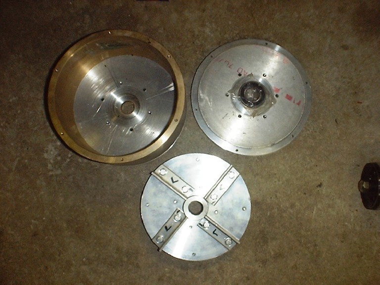
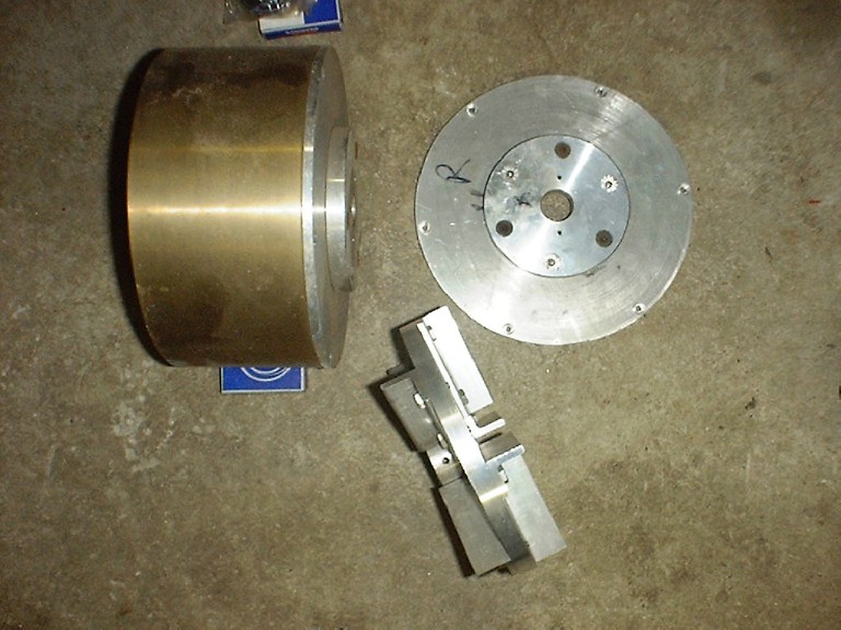
I just laid one of the bearings in the wrapper on the end plate for show. The bearings I had purchased were some highspeed precision ones for a 1" shaft.
Looking back after reading all the new info on the forum about water brakes I would do ALOT different like the housing width and the rotor. The inside dia of the housing is 8". The housing is some mystery metal and weighs a TON but at the time I could not find any alum thickwall pipe.
Edited By bruce on 1167958990
I still have the end plates w/bearings and the housing, I'll see if I can get some pics posted up in the next day or two.
For someone that has a mill and rotary table the rotor would not be all that hard to machine from billet using a ball and regular end mill. Maybe a couple hours? Turn it to size first on the lathe bore the shaft hole and broach a keyway, makeup a fixture to register off the bored hole and keyway so both sides would have the fins machined in relation to each side. Your side plates could be machined the same way so you would not have to work with a soild 2" or 3" peice of billet or bolt them to thinner side plates. If you made it modular and you screwed up any part along the way you would not be scraping the whole thing (this was my thinking, hate making scrap parts)
A casting for the rotor would be nice but I think it presents some issues on the machining end specially when it comes to sand casting and core shifts. How will you verify the balance of the fins ie that the fins are in relation to the axis of the shaft hole? If you are going to spin the dyno at any high rpm this will be an issue I would think? The housing would be good as a casting since you can just machine the fins off for thickness in relation the shaft holes and there is no rotation issue to contend with just rotor clearance.
Anyways these are just some of my thoughts . . . more brainstorming than actual engineering/machining data . . . I have a local scrapyard with billet alum so price of material is not a big issue as long as they have whatca need for a given project, I tend to find myself in the scrapyard figuring out how I can make something from the stuff I find . . . kinda backwards I know.
Ok here are some pics of what I had:
I just laid one of the bearings in the wrapper on the end plate for show. The bearings I had purchased were some highspeed precision ones for a 1" shaft.
Looking back after reading all the new info on the forum about water brakes I would do ALOT different like the housing width and the rotor. The inside dia of the housing is 8". The housing is some mystery metal and weighs a TON but at the time I could not find any alum thickwall pipe.
Edited By bruce on 1167958990
"There is no more formidable adversary than one who perceives he has nothing to lose." - Gen. George S. Patton
- bruce
- Site Admin
- Posts: 1638
- Joined: Sun May 09, 2004 12:17 pm
![]() by Tony » Fri Jan 05, 2007 5:33 pm
by Tony » Fri Jan 05, 2007 5:33 pm
The rotor (and end housings) do not require a central core, as neither part needs to be made hollow. So core shift is just not possible. The shape of both the rotor, and the housings are about the simplest shape imaginable for sand casting.
I agree that attaching the rotor onto the shaft presents some rather interesting problems, as both shaft and rotor will run wet. Any junction of dissimilar metals will have a rather high tendency towards corrosion, especially in hot, oxygen rich, untreated water.
Initially I would just build a prototype out of aluminium with a mild steel shaft and a keyway. Provided the rotor hub was made fairly beefy, it should work fine. But I would expect the whole thing to corrode away fairly quickly due to the electrolytic action of dissimilar metals immersed in some fairly hot highly turbulent water.
One solution to this, would be to fabricate a one piece rotor and hollow shaft assembly. That could extended right out through and beyond the seals and bearings. A solid steel drive shaft could then run through the middle for support, but it, and any taper lock fitting, splines, or a keyway could then run dry.
Another way would be to just use suitable corrosion resistant materials such as brass, marine bronze or stainless steel. For a sand cast rotor and end housings, that would present no problem at all.
Also known as the infamous "Warpspeed" on some other Forums.
- Tony
- Posts: 824
- Joined: Sat Dec 03, 2005 12:34 pm
- Location: Melbourne, Australia
21 posts
• Page 1 of 2 • 1, 2
Who is online
Users browsing this forum: No registered users and 2 guests