
I am making a program for my rolling road and we are trying to get the computer to regulate the brake. I am using a card with digital input and output and one output with pwm.
I have found a regulator with this function (pwm) but it is for only 24V, I need something that can take 230V. Is there anyone who knows where I can find that?? Or maybe someone have a better idea about how to regulate the brake from the computer??
Pulse width modulated power control
40 posts
• Page 1 of 3 • 1, 2, 3
![]() by Tony » Fri Nov 09, 2007 6:09 pm
by Tony » Fri Nov 09, 2007 6:09 pm
Funnily enough, just last week I obtained a bare chassis roller dyno with an eddy current retarder, but without any other control electronics to go with it. So I am going through exactly the same exercise myself right now.
The commercial dynos all seem to use a phase controlled SCR rectifier bridge direct off the mains to control the dc current through the retarder.
The only commercial unit I am aware of specifically to do this is produced by a company called Sport Devices:
They make an interesting little accessory box that goes with their own SP-4 dyno control computer system:
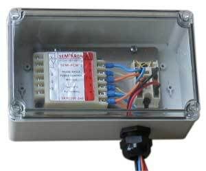
Looking at that picture, they have just used a pair of standard off the shelf Semikron modules that they have wired up themselves and fitted into a standard plastic electrical enclosure.
You could probably buy the whole box as shown in the picture from Sport Devices, or better still, buy the bare modules from Semikron for possibly around half the cost.
The power module on the right looks to me like an SKCH 28:
This is a half controlled bridge (two SCRs, two diodes) and it also has a third flywheel diode required for highly inductive loads such as an eddy current retarder. There are several different versions of this type of module available for driving different types of loads. The SKCH has this extra diode fitted across the output, and this extra diode is important when driving inductive loads.
The left hand control module I cannot identify, it must be more recent than my ancient 1993 Semikron data book, and the picture is too fuzzy to read the part number from.
But it will be a readily obtained off the shelf standard part available from any Semikron agent world wide.
Myself, I am going to design and build my own power control system completely from scratch. I have a few rather unconventional ideas I would like to try.
Using the above commercial modules would be the simpler way to do this, but I am going to try to find a lower cost solution with perhaps better dynamic performance.
The commercial dynos all seem to use a phase controlled SCR rectifier bridge direct off the mains to control the dc current through the retarder.
The only commercial unit I am aware of specifically to do this is produced by a company called Sport Devices:
They make an interesting little accessory box that goes with their own SP-4 dyno control computer system:
Looking at that picture, they have just used a pair of standard off the shelf Semikron modules that they have wired up themselves and fitted into a standard plastic electrical enclosure.
You could probably buy the whole box as shown in the picture from Sport Devices, or better still, buy the bare modules from Semikron for possibly around half the cost.
The power module on the right looks to me like an SKCH 28:
This is a half controlled bridge (two SCRs, two diodes) and it also has a third flywheel diode required for highly inductive loads such as an eddy current retarder. There are several different versions of this type of module available for driving different types of loads. The SKCH has this extra diode fitted across the output, and this extra diode is important when driving inductive loads.
The left hand control module I cannot identify, it must be more recent than my ancient 1993 Semikron data book, and the picture is too fuzzy to read the part number from.
But it will be a readily obtained off the shelf standard part available from any Semikron agent world wide.
Myself, I am going to design and build my own power control system completely from scratch. I have a few rather unconventional ideas I would like to try.
Using the above commercial modules would be the simpler way to do this, but I am going to try to find a lower cost solution with perhaps better dynamic performance.
Also known as the infamous "Warpspeed" on some other Forums.
- Tony
- Posts: 824
- Joined: Sat Dec 03, 2005 12:34 pm
- Location: Melbourne, Australia
![]() by Tony » Fri Nov 09, 2007 7:08 pm
by Tony » Fri Nov 09, 2007 7:08 pm
I have now identified that Semikron control module, the basic part number is SKPC200, and it comes in three different voltage supply ratings. It requires a dc 0-5v input voltage to control it.
SKPC200-115
SKPC200-240
SKPC200-440
Download the PDF file. On page two there are two wiring diagrams called "half controlled bridge". These will convert the ac mains voltage into a variable dc supply to power your retarder. The maximum dc output voltage will be roughly about 15% lower than the incoming ac mains supply voltage. Current through the retarder can be adjusted up and down by the potentiometer VR1, or an incoming dc control voltage of 0 to +5 volts will do the same thing.
This is the simplest store bought off the shelf solution. Not exactly low cost, or the ultimate in performance, but it would save a lot of work.
Also known as the infamous "Warpspeed" on some other Forums.
- Tony
- Posts: 824
- Joined: Sat Dec 03, 2005 12:34 pm
- Location: Melbourne, Australia
![]() by tweaks » Fri Nov 09, 2007 10:23 pm
by tweaks » Fri Nov 09, 2007 10:23 pm
Hi Tony ,
What make of dyno is it a Vane or ? and what size Telma is fitted the frame..there must be a pile of these hidden away in some corner or Dyno Dynamics, DTS ect have traded and then scrapped them...
Sounds an interesting project, wish I had some time to get around to completing mine.
Cheers
Lynds
What make of dyno is it a Vane or ? and what size Telma is fitted the frame..there must be a pile of these hidden away in some corner or Dyno Dynamics, DTS ect have traded and then scrapped them...
Sounds an interesting project, wish I had some time to get around to completing mine.
Cheers
Lynds
- tweaks
- Posts: 20
- Joined: Mon Jul 09, 2007 11:35 pm
- Location: Melbourne . Australia
![]() by tweaks » Sun Nov 11, 2007 10:18 pm
by tweaks » Sun Nov 11, 2007 10:18 pm
Tony ,
will the unit be able to control the rate of acceleration ( 600 revs / sec ect ) and also be able to hold engine at pre determined rev points to enable fuel injection lambda to be read and set easily.
I have been looking at Sports Devices unit , they seem to have a good software package with but the $$$$ is the stumbling block .
I had also been looking through RS Components dogalog at various controllers but decided my lack of electronics expertise was lacking ( if it was the old Festo air controllers thats a different thing ) and my guru friend who owes me a big favour is playing hard to get.
Cheers
Lynds
- tweaks
- Posts: 20
- Joined: Mon Jul 09, 2007 11:35 pm
- Location: Melbourne . Australia
![]() by Tony » Sun Nov 11, 2007 11:36 pm
by Tony » Sun Nov 11, 2007 11:36 pm
The biggest problem with controlling something like an eddy current retarder is the absolutely huge amount of stored magnetic energy involved. The whole thing is just an enormous electromagnet with a few hundred Kg of iron and steel.
Think of it being rather like a very large tank full of water, or a very heavy flywheel. Not possible to instantly fill a tank, or instantly accelerate a flywheel. Emptying, or slowing, is just as challenging a problem.
Getting it to respond quickly enough to change is the difficult part. If you just want to do some steady state engine tuning, and set up some sort of fairly fixed road load, slow retarder speed of response is not going to be an issue.
It does however start to become a real problem if you wish to very rapidly control or change the effective dyno speed or load on the fly. It is simply not possible to instantly increase or decrease the current flowing through the retarder windings. The retarder current will always ramp up, and ramp down at some rate determined by the electrical characteristics of both the retarder itself, and the dc power supply controlling it.
This electrical time lag in retarder response, depends mainly on the dc power supply voltage, and how the windings are connected (within the retarder), and the electrical resistance of the actual windings.
I have been doing some electrical tests here, now that I actually have a retarder to play with. So far I have tried quite a few combinations of phase controlled rectifier, that is what all the commercial dynos appear to use.
Next week I intend try out a few more radical ideas with high frequency pulse width modulation, which should in theory be able to give slightly more desirable control characteristics.
But for acceleration sweep testing, the high mechanical inertia of both rollers and retarder are going to create another problem, quite apart from electrical delay in the retarder itself. I believe that the better quality commercial dynos are able to compensate for all this in software. What comes out of the torque measurement is modified somehow to give a truer reading of actual tractive effort during rapid acceleration. How this is actually done I do not know, but it would have to take into account total inertia, as well as predictively control the retarder current ahead of time. All possible, but far from easy to implement. The dyno manufacturers are not likely to tell you all about what they themselves have probably spent years developing.
Building something that works is not difficult. Building something that works extremely well is another matter altogether. It is one reason why commercial dynos are so expensive.
Also known as the infamous "Warpspeed" on some other Forums.
- Tony
- Posts: 824
- Joined: Sat Dec 03, 2005 12:34 pm
- Location: Melbourne, Australia
![]() by Tony » Mon Nov 12, 2007 3:29 am
by Tony » Mon Nov 12, 2007 3:29 am
O/k here is problem number one. Let's first assume we connect the sixteen coils of a typical Telma retarder into a single series string.
That then requires 16 x 12v = 192 volts.
All these retarders have twelve volt coils, but the current rating depends on the size of the particular retarder. Current per coil falls between around ten amps to twenty amps per coil. Let's assume twelve amps in this example to keep the figures simple.
Each coil will have a resistance of one ohm (12v/12A), and sixteen coils in series will have a resistance of sixteen ohms.
Now let's say we have a 240V rms incoming mains supply, that is the root mean square voltage (rms), but we are interested in the average dc voltage after this 240v is rectified. The rms voltage is 1.11 times greater than the average. So for 240v rms ac into our rectifier, we expect to get 216 volts dc, (neglecting voltage drops across the rectifier diodes). That is reasonably close to 192 volts, so that is what we will use here initially for our example.
Fine, so we hook up our 240 volt mains supply and full wave dc bridge rectifier to our 192 volt connected Telma, and close the switch.
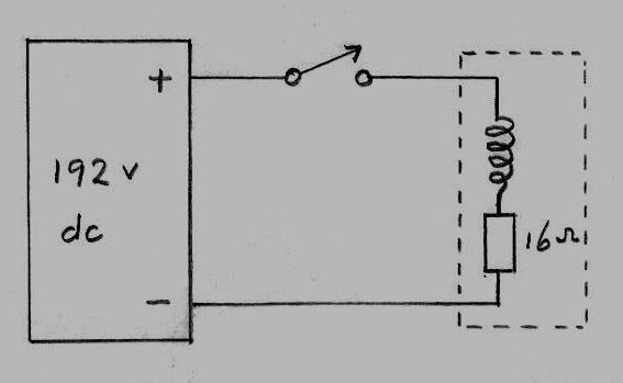
Initially the full 192 volts appears across the coil, and the current starts to rise. As the current through the coils increases, a voltage starts to drop across the 16 ohm resistor. This voltage drop lost across the resistor, reduces the available voltage across the coil which is what sets the rate of current increase. This in turn slows the rate of current rise. Eventually the rate of increase is zero and we reach the steady state final current.
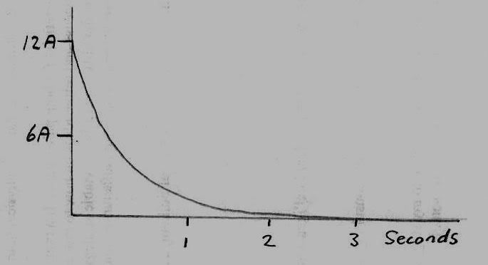
Eventually the current stabilizes according to ohms law at the full twelve amps. Something like this for a typical Telma:
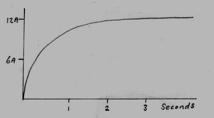
The initial rate of rise is reasonably rapid, but it can take a couple of seconds to reach something approaching full rated current. This feels pretty good in a truck going down a hill, but is less than wonderful for rapidly controlling a dyno load.
It is normal practice to connect a diode across the winding, so that when the switch is opened, there is not a tremendous welding arc developed across the switch.
When the power is removed by opening the switch, the circuit looks like this:
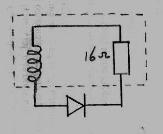
The twelve amps flowing through the winding circulates through the diode and the sixteen ohm resistance of the windings. This current is maintained by the collapsing magnetic field, and the rate of collapse is set by the allowable voltage across the winding. This voltage will be the voltage drop across the resistor plus the voltage drop across the diode.
Initially the voltage drop across both the resistance and the coils will be the full 192 volts, and current fall will be fairly fast. But as the current diminishes, so to will the voltage across the winding which decreases the rate of current fall.
Even though the switch opens instantly, the rate of current fall looks like this:
The rate of both rise and fall will look similar in this example, because the same voltage and resistance are present during both turn on and turn off. Again this would work wonderfully well in a truck, but would not be so fast responding for a dyno application.
There are a number of ways to go about improving this sluggish behavior, but all involve raising the voltages across the windings during times of rapid change.
This is only an introduction to the problem of sluggish retarder response time.
More on this later.
That then requires 16 x 12v = 192 volts.
All these retarders have twelve volt coils, but the current rating depends on the size of the particular retarder. Current per coil falls between around ten amps to twenty amps per coil. Let's assume twelve amps in this example to keep the figures simple.
Each coil will have a resistance of one ohm (12v/12A), and sixteen coils in series will have a resistance of sixteen ohms.
Now let's say we have a 240V rms incoming mains supply, that is the root mean square voltage (rms), but we are interested in the average dc voltage after this 240v is rectified. The rms voltage is 1.11 times greater than the average. So for 240v rms ac into our rectifier, we expect to get 216 volts dc, (neglecting voltage drops across the rectifier diodes). That is reasonably close to 192 volts, so that is what we will use here initially for our example.
Fine, so we hook up our 240 volt mains supply and full wave dc bridge rectifier to our 192 volt connected Telma, and close the switch.
Initially the full 192 volts appears across the coil, and the current starts to rise. As the current through the coils increases, a voltage starts to drop across the 16 ohm resistor. This voltage drop lost across the resistor, reduces the available voltage across the coil which is what sets the rate of current increase. This in turn slows the rate of current rise. Eventually the rate of increase is zero and we reach the steady state final current.
Eventually the current stabilizes according to ohms law at the full twelve amps. Something like this for a typical Telma:
The initial rate of rise is reasonably rapid, but it can take a couple of seconds to reach something approaching full rated current. This feels pretty good in a truck going down a hill, but is less than wonderful for rapidly controlling a dyno load.
It is normal practice to connect a diode across the winding, so that when the switch is opened, there is not a tremendous welding arc developed across the switch.
When the power is removed by opening the switch, the circuit looks like this:
The twelve amps flowing through the winding circulates through the diode and the sixteen ohm resistance of the windings. This current is maintained by the collapsing magnetic field, and the rate of collapse is set by the allowable voltage across the winding. This voltage will be the voltage drop across the resistor plus the voltage drop across the diode.
Initially the voltage drop across both the resistance and the coils will be the full 192 volts, and current fall will be fairly fast. But as the current diminishes, so to will the voltage across the winding which decreases the rate of current fall.
Even though the switch opens instantly, the rate of current fall looks like this:
The rate of both rise and fall will look similar in this example, because the same voltage and resistance are present during both turn on and turn off. Again this would work wonderfully well in a truck, but would not be so fast responding for a dyno application.
There are a number of ways to go about improving this sluggish behavior, but all involve raising the voltages across the windings during times of rapid change.
This is only an introduction to the problem of sluggish retarder response time.
Also known as the infamous "Warpspeed" on some other Forums.
- Tony
- Posts: 824
- Joined: Sat Dec 03, 2005 12:34 pm
- Location: Melbourne, Australia
![]() by bruce » Mon Nov 12, 2007 6:04 pm
by bruce » Mon Nov 12, 2007 6:04 pm
My head hurts already!! 
This is going to be an interesting class though . . . and to think Tony you got me up and running with a variac with my setup.
My retarder uses 72volts at 40amps for 280lb ft full load.
This is going to be an interesting class though . . . and to think Tony you got me up and running with a variac with my setup.
My retarder uses 72volts at 40amps for 280lb ft full load.
"There is no more formidable adversary than one who perceives he has nothing to lose." - Gen. George S. Patton
- bruce
- Site Admin
- Posts: 1638
- Joined: Sun May 09, 2004 12:17 pm
![]() by tweaks » Mon Nov 12, 2007 6:49 pm
by tweaks » Mon Nov 12, 2007 6:49 pm
Tony ....thanks for that explanation , I can now see what we are up against in trying to get our systems up to where we would like them.
As you say the Telma/retarders work well in the transport enviroment,where I have had experience in the installation and operation of various units on garbage trucks and library busses.
I look forward to our next lesson .
Cheers
Lynds
PS. What side of Melbourne you on Tony
As you say the Telma/retarders work well in the transport enviroment,where I have had experience in the installation and operation of various units on garbage trucks and library busses.
I look forward to our next lesson .
Cheers
Lynds
PS. What side of Melbourne you on Tony
- tweaks
- Posts: 20
- Joined: Mon Jul 09, 2007 11:35 pm
- Location: Melbourne . Australia
![]() by Tony » Mon Nov 12, 2007 8:02 pm
by Tony » Mon Nov 12, 2007 8:02 pm
Here comes the next piece of the puzzle.
To automatically control the dyno load, we need to have some type of closed control loop that will adjust the current through the retarder coils to give us the desired operating speed.
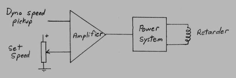
The dynamic characteristics of this control amplifier are very important and will be mentioned later, but at this stage I only wish to discuss the power system requirement part of it, that provides the high current to the retarder coils.
The Amplifier section just compares the actual running speed to the desired running speed, and produces an output voltage proportional to the detected speed error. The amplifier is the "brain" and the power system the "muscle" to control the retarder.
Where there is a speed difference present, the amplifier gain can be increased to produce a much larger signal to the power system, but the power system needs to have enough "grunt and speed" to do the job required of it.
The amplifier will be able drive the power system very hard in either direction, and this can very greatly speed up the response of an otherwise sluggish retarder.
It is a rather like going full throttle in your car to accelerate from 50 Mph to 55mph, then backing right off when you reach 55mph. Acceleration time will be much shorter than if you just open the throttle the small extra amount required, and let the speed very slowly build up to 55 mph.
This works fine at low current levels into the retarder, because the voltage applied to the retarder by the power system can be driven right up to full maximum very briefly, causing speed of current rise through the retarder coils to be greatly increased. The problem is, that when operating up near maximum, there is no extra reserve of additional voltage available to speed things up. The power system runs out of voltage head room and "grunt".
The solution is to build a power system with a much higher available voltage than the retarder requires to run normally at full output. About twice the voltage should work very well. So if your dc power supply is say 200 volts, instead of connecting up your retarder to run at 200 volts, you connect it up to run at 100 volts.
This greatly improves the response speed for rising current. if you want to quickly go from 95% retarder current (95 volts) to 100 % retarder current (100 volts) the control amplifer could briefly drive the control voltage up to the full 200 for a brief instant. As soon as the required retarder current is reached, the amplifier "throttles back" and the system then runs at it's full rated voltage and current of 100 volts.
So the trick for greatly improving the response time (in the rising direction only) is to set up your retarder to run at something like half the full available dc voltage. The closed control loop will ensure that the retarder is never overloaded from excessive current, but it can for very brief periods of change provide excess voltage to very greatly speed up the response time.
The only disadvantage is that by connecting the retarder to run at a lower voltage, the required peak current will be higher. But that is the price you pay for improved response speed.
Depending where you are, in Europe, Australia and the UK, around 380v to 415 volts ac are available between two phases. A retarder connected in full series for 192 volts dc should work well.
In the US there is around 208 volts phase to phase, and in most other places 220v to 240v phase to neutral. A retarder wired in series parallel for 96 volts might be a reasonable choice.
For America and Japan if there is only a single phase, 48 volt connection of the retarder might be the only choice, but the required current will be extremely high.
In summary, if response speed is not important to you, just wire your retarder to suit the full available dc supply voltage. To really speed things up, run your retarder within a closed control loop, and wire your retarder for perhaps around roughly half the full available dc voltage, it will make a very big difference. The higher the excess voltage available, the faster it will respond in the increasing load direction.
Decreasing retarder current requires getting rid of a lot of stored magnetic energy, which is an entirely different problem to quickly building this stored magnetic energy up. Higher operating voltage gives you a bigger "engine", improving the "brakes" to rapidly dissipate all this stored magnetic energy is a separate and quite different problem.
To automatically control the dyno load, we need to have some type of closed control loop that will adjust the current through the retarder coils to give us the desired operating speed.
The dynamic characteristics of this control amplifier are very important and will be mentioned later, but at this stage I only wish to discuss the power system requirement part of it, that provides the high current to the retarder coils.
The Amplifier section just compares the actual running speed to the desired running speed, and produces an output voltage proportional to the detected speed error. The amplifier is the "brain" and the power system the "muscle" to control the retarder.
Where there is a speed difference present, the amplifier gain can be increased to produce a much larger signal to the power system, but the power system needs to have enough "grunt and speed" to do the job required of it.
The amplifier will be able drive the power system very hard in either direction, and this can very greatly speed up the response of an otherwise sluggish retarder.
It is a rather like going full throttle in your car to accelerate from 50 Mph to 55mph, then backing right off when you reach 55mph. Acceleration time will be much shorter than if you just open the throttle the small extra amount required, and let the speed very slowly build up to 55 mph.
This works fine at low current levels into the retarder, because the voltage applied to the retarder by the power system can be driven right up to full maximum very briefly, causing speed of current rise through the retarder coils to be greatly increased. The problem is, that when operating up near maximum, there is no extra reserve of additional voltage available to speed things up. The power system runs out of voltage head room and "grunt".
The solution is to build a power system with a much higher available voltage than the retarder requires to run normally at full output. About twice the voltage should work very well. So if your dc power supply is say 200 volts, instead of connecting up your retarder to run at 200 volts, you connect it up to run at 100 volts.
This greatly improves the response speed for rising current. if you want to quickly go from 95% retarder current (95 volts) to 100 % retarder current (100 volts) the control amplifer could briefly drive the control voltage up to the full 200 for a brief instant. As soon as the required retarder current is reached, the amplifier "throttles back" and the system then runs at it's full rated voltage and current of 100 volts.
So the trick for greatly improving the response time (in the rising direction only) is to set up your retarder to run at something like half the full available dc voltage. The closed control loop will ensure that the retarder is never overloaded from excessive current, but it can for very brief periods of change provide excess voltage to very greatly speed up the response time.
The only disadvantage is that by connecting the retarder to run at a lower voltage, the required peak current will be higher. But that is the price you pay for improved response speed.
Depending where you are, in Europe, Australia and the UK, around 380v to 415 volts ac are available between two phases. A retarder connected in full series for 192 volts dc should work well.
In the US there is around 208 volts phase to phase, and in most other places 220v to 240v phase to neutral. A retarder wired in series parallel for 96 volts might be a reasonable choice.
For America and Japan if there is only a single phase, 48 volt connection of the retarder might be the only choice, but the required current will be extremely high.
In summary, if response speed is not important to you, just wire your retarder to suit the full available dc supply voltage. To really speed things up, run your retarder within a closed control loop, and wire your retarder for perhaps around roughly half the full available dc voltage, it will make a very big difference. The higher the excess voltage available, the faster it will respond in the increasing load direction.
Decreasing retarder current requires getting rid of a lot of stored magnetic energy, which is an entirely different problem to quickly building this stored magnetic energy up. Higher operating voltage gives you a bigger "engine", improving the "brakes" to rapidly dissipate all this stored magnetic energy is a separate and quite different problem.
Also known as the infamous "Warpspeed" on some other Forums.
- Tony
- Posts: 824
- Joined: Sat Dec 03, 2005 12:34 pm
- Location: Melbourne, Australia
![]() by bruce » Mon Nov 12, 2007 9:22 pm
by bruce » Mon Nov 12, 2007 9:22 pm
I'm going to go sleep in the back of the class . . . wake me up when you get it all sorted out it's way over my head!
I have an old motor control here that you set max rpm's with it has speed sense input, you can set the ramp-up time. That's how I was going to go but if you figure something else out . . . just give my chair a kick and wake me back up in time for the labwork.
I have an old motor control here that you set max rpm's with it has speed sense input, you can set the ramp-up time. That's how I was going to go but if you figure something else out . . . just give my chair a kick and wake me back up in time for the labwork.
"There is no more formidable adversary than one who perceives he has nothing to lose." - Gen. George S. Patton
- bruce
- Site Admin
- Posts: 1638
- Joined: Sun May 09, 2004 12:17 pm
![]() by Tony » Mon Nov 12, 2007 9:54 pm
by Tony » Mon Nov 12, 2007 9:54 pm
Part three, the SCR phase controlled rectifier.
Most of us are probably familiar with the humble bridge rectifier, where four diodes turn an incoming ac supply into a dc supply.
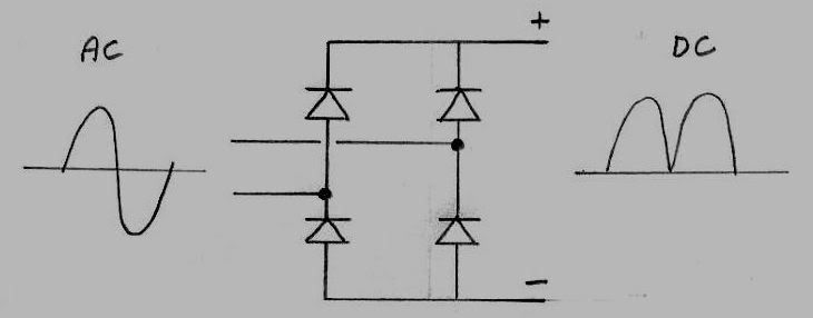
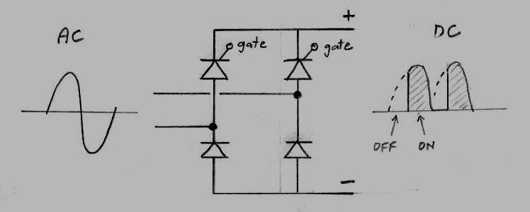
If two ordinary rectifier diodes are replaced with SCRs (silicon controlled rectifiers) we can control the output voltage from zero to maximum. These SCRs normally remain off in both directions, but when the gate pin is triggered with a brief pulse, the SCR turns on, and remains on until the voltage across it is reduced to zero, where it turns off.
By varying the gate trigger timing, these SCRs can remain off for the first part of each ac half cycle, then be triggered on for the remaining part of each half cycle. The earlier the trigger arrives, the greater the output dc power will be.
Additional electronics are required to turn an incoming dc control voltage from the control system into suitably timed gate trigger pulses for the SCRs, but commercial modules such as the Semikron part mentioned in an earlier post are available to do this.
So really the power system is just a matter of rewiring your retarder to the required dc voltage, and obtaining a suitable control module and an SCR bridge. How fast it can respond in the increasing current direction depends on the relative voltages.
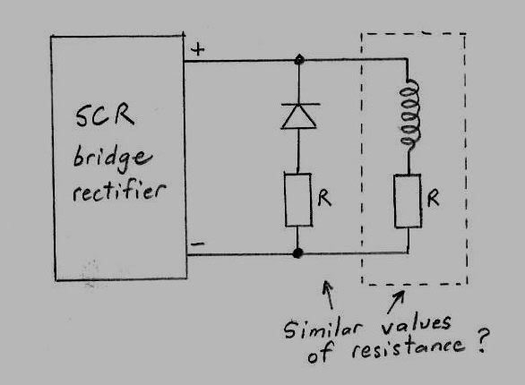
Getting a similar fast response in the decreasing direction is another matter altogether. Rearranging the retarder coils to suit different voltages will not significantly effect the rate of current reduction if the usual diode is used to re-direct current flow after the rectifier bridge has turned off. As with getting a fast increasing response, the trick to getting just as fast decrease in stored magnetic flux is in raising the voltage. This can be done in two different ways.
The simplest is to just add some additional resistance in series with the diode connected across the retarder. As the magnetic flux collapses, current is driven around this circuit, which includes the resistance of the coils themselves, and this additional resistor. The greater this resistance, the higher the developed voltage across both these resistors combined, and the faster the magnetic flux will diminish. All that stored energy is dissipated in these resistors. A reasonable rule of thumb might be to fit a resistor roughly equal to the combined resistance of all the retarder coils (in the particular way they are connected).
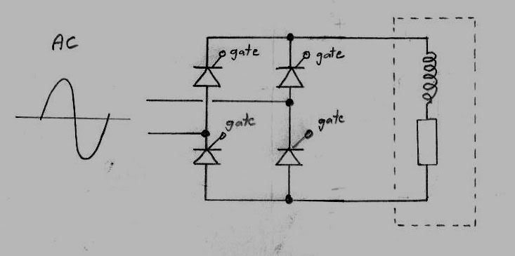
The other way to speed up the rate of magnetic flux reduction is to use four SCRs in the rectifier bridge, instead of two. With this system no diode is used across the retarder, and the retarder can dump it's energy back into the mains supply. This is the very fastest method of reducing the stored energy in the retarder, because the voltage across the retarder is actually reversed and driven in the opposite direction on the opposite halves of each mains cycle.
It does require a full bridge of four SCRs and an appropriate type of trigger module with four gate drivers. I built my own to test this with, but commercial modules are probably ? available, although I have not tracked anything down.
Here is what the full bridge power system would look like:
Sorry this is all so long winded, but there are quite a few problems to overcome, and there are a variety of ways of going about this, depending on how much performance, and how much complexity you wish to get involved with.
A simple engine tuning dyno is one thing, performing ramp testing, or synchronizing two dynos for 4WD requires much faster responding load control than might be obtained by a very basic system.
Again my apologies for all the excess verbiage.
Most of us are probably familiar with the humble bridge rectifier, where four diodes turn an incoming ac supply into a dc supply.
If two ordinary rectifier diodes are replaced with SCRs (silicon controlled rectifiers) we can control the output voltage from zero to maximum. These SCRs normally remain off in both directions, but when the gate pin is triggered with a brief pulse, the SCR turns on, and remains on until the voltage across it is reduced to zero, where it turns off.
By varying the gate trigger timing, these SCRs can remain off for the first part of each ac half cycle, then be triggered on for the remaining part of each half cycle. The earlier the trigger arrives, the greater the output dc power will be.
Additional electronics are required to turn an incoming dc control voltage from the control system into suitably timed gate trigger pulses for the SCRs, but commercial modules such as the Semikron part mentioned in an earlier post are available to do this.
So really the power system is just a matter of rewiring your retarder to the required dc voltage, and obtaining a suitable control module and an SCR bridge. How fast it can respond in the increasing current direction depends on the relative voltages.
Getting a similar fast response in the decreasing direction is another matter altogether. Rearranging the retarder coils to suit different voltages will not significantly effect the rate of current reduction if the usual diode is used to re-direct current flow after the rectifier bridge has turned off. As with getting a fast increasing response, the trick to getting just as fast decrease in stored magnetic flux is in raising the voltage. This can be done in two different ways.
The simplest is to just add some additional resistance in series with the diode connected across the retarder. As the magnetic flux collapses, current is driven around this circuit, which includes the resistance of the coils themselves, and this additional resistor. The greater this resistance, the higher the developed voltage across both these resistors combined, and the faster the magnetic flux will diminish. All that stored energy is dissipated in these resistors. A reasonable rule of thumb might be to fit a resistor roughly equal to the combined resistance of all the retarder coils (in the particular way they are connected).
The other way to speed up the rate of magnetic flux reduction is to use four SCRs in the rectifier bridge, instead of two. With this system no diode is used across the retarder, and the retarder can dump it's energy back into the mains supply. This is the very fastest method of reducing the stored energy in the retarder, because the voltage across the retarder is actually reversed and driven in the opposite direction on the opposite halves of each mains cycle.
It does require a full bridge of four SCRs and an appropriate type of trigger module with four gate drivers. I built my own to test this with, but commercial modules are probably ? available, although I have not tracked anything down.
Here is what the full bridge power system would look like:
Sorry this is all so long winded, but there are quite a few problems to overcome, and there are a variety of ways of going about this, depending on how much performance, and how much complexity you wish to get involved with.
A simple engine tuning dyno is one thing, performing ramp testing, or synchronizing two dynos for 4WD requires much faster responding load control than might be obtained by a very basic system.
Again my apologies for all the excess verbiage.
Also known as the infamous "Warpspeed" on some other Forums.
- Tony
- Posts: 824
- Joined: Sat Dec 03, 2005 12:34 pm
- Location: Melbourne, Australia
40 posts
• Page 1 of 3 • 1, 2, 3
Who is online
Users browsing this forum: No registered users and 1 guest