
Pulse width modulated power control
40 posts
• Page 2 of 3 • 1, 2, 3
![]() by bruce » Mon Nov 12, 2007 10:10 pm
by bruce » Mon Nov 12, 2007 10:10 pm
No apologies required! We have plenty of space on the server, go on Professor Tony at your leisure . . .
"There is no more formidable adversary than one who perceives he has nothing to lose." - Gen. George S. Patton
- bruce
- Site Admin
- Posts: 1638
- Joined: Sun May 09, 2004 12:17 pm
![]() by Tony » Mon Nov 12, 2007 11:48 pm
by Tony » Mon Nov 12, 2007 11:48 pm
Controlling the current flow through the retarder up and down rapidly enough and accurately enough is probably the biggest problem most of us are going to face. Even some expensive commercial dynos are reputed to sometimes have rather wobbly speed control, so all this is not as simple or easy as it might at first appear.
But if you have succeeded in building a dc power system that responds very rapidly in both directions, the only other thing required to finish the job is the closed loop control amplifier tuning.
It basically comes down to how much and how quickly you can apply corrections without the whole closed loop system becoming unstable. This is basically what is known as a "PID controller". Proportional, Integral, Derivative, but most controllers are usually just "PI" with no derivative action.
This "PI" controller could be written in software, built with ordinary electronic component parts, or purchased as yet another ready built commercial module.
After years of playing around with these PID controllers, I will let you into a few hard won secrets. People get into horrible trouble trying to successfully tune these controllers, when the problem is really not with the controller tuning, but with the system being controlled.
The "how much" and "how quickly" control corrections can be applied, is the whole key to getting nice tight accurate dyno speed control, without speed wobbles or instability. But the controller itself is only one part of the whole closed loop.
If the rest of the system has characteristics that vastly change from one operating point to another, then no state of tuning can be ideal everywhere. That is a fundamental truth.
First take the "how much" correction part. Suppose you have a system that was grossly non linear. At one end of the control range the system is extremely sensitive to change, at the other end of the control range, massive controller input is required to get any response in output at all.
So you start playing around with the "P" or proportional gain part of your PID controller. As you increase the gain setting, the system becomes unstable at one end, because of the extreme sensitivity. But at the other end, there is simply not enough gain to control properly. So you get awful results no matter where the gain is set.
The solution to a problem like that is to make damned sure the system is linear, or reasonably linear. If it ain't, fix it so it is.
Ideally there should be an almost direct relationship between the control voltage going into the power stage, and the resulting current flowing in the retarder coils. If that is right, the "P" gain term in the controller can be set to an optimum value, and the system will behave very well everywhere.
The "how quickly" part is the "I" or integral term. This has to do with delays in the system. The controller makes a change, and it has to wait briefly to let that change take effect before making a further change. This is actually a continuous process, but it could probably be thought of as "waiting".
If the controller responds too slowly to change, it is obviously going to make the whole system sluggish to respond. But if it responds too quickly it can apply too much correction and result in some overshoot in the opposite direction. It then over corrects , and the system can go into wild and ever increasing alternate swings. Setting the "I" term is a case of compromise to get fastest response without instability.
Now suppose your retarder responds very quickly in some circumstances, and very slowly in other circumstances. The response speed may be very different going up with increasing current, and coming down with decreasing current, and it will almost certainly respond differently to change at different current values.
When tuning the "I" term of your PID controller, it will need to be tuned to the most sluggish condition of the retarder. If you can build a retarder power unit that is sufficiently fast everywhere under all conditions, you can really get some performance out of your PID controller. Otherwise you will need to detune the PID to cater for the slowest condition if instability is to be avoided.
There is a lot to be gained by really putting some effort into the design of the power stage to make it both linear and fast in both directions. If that is done, the PID can be adjusted for really good performance. If the power stage is really crappy, nothing you can do to the PID tuning is going to fix it.
That is why I am being really pedantic and anal about the power controller, it is extremely important to get the best results.
Also known as the infamous "Warpspeed" on some other Forums.
- Tony
- Posts: 824
- Joined: Sat Dec 03, 2005 12:34 pm
- Location: Melbourne, Australia
![]() by CraigAPD » Fri Jan 04, 2008 4:17 pm
by CraigAPD » Fri Jan 04, 2008 4:17 pm
This makes for excellent reading, it has really filled in a few gaps in the info ive been gathering from the net/dyno manufacturers.
Ive got a Telma F5750 retarder which im building into an old Clayton (previously water-brake) chassis dyno. Im planning on purchasing the required hardware/software from Land&Sea, though im about to gather some info on Sportsdevices tommorow.
@ Tony, do you have any experience of these two control systems? any advice/comments on them??
Thanks for the intresting/informative read,
Craig
- CraigAPD
- Posts: 24
- Joined: Fri Jan 04, 2008 2:44 pm
- Location: England
![]() by Tony » Fri Jan 04, 2008 5:42 pm
by Tony » Fri Jan 04, 2008 5:42 pm
Craig, apart from looking at various web pages, I have no direct experience with either software vendor.
All of the commercial dyno software packages that I am aware of, are purely for monitoring the output from a dyno. In other words, they just take torque and rpm measurements, and produce and display some fancy curves and displays from those two inputs.
They are providing a fairly universal software product, and that same software will work on just about any size or type of dyno.
What they do not usually provide, is for any means of controlling your dyno. For that, you are completely on your own. They cannot provide a dyno control system, simply because they have absolutely no idea what size or type of dyno you have, or what it is to be used for. It could be an engine or a roller dyno, or even a mini table top dyno for small radio controlled models. The braking could be by by inertia, water brake, eddy current, or friction brake.
Whatever controls your dyno will need to be very specific for the type of dyno, and the type of testing you plan to use it for. A universal dyno control box is simply not really possible.
The commercial dyno software is a great way to monitor your dyno output, but leaves you with absolutely nothing to control your dyno. But at least it solves half of the problem.
Some of the commercial dyno packages may have some very basic outputs for dyno control, but check to see if these are suitable for your intended purpose, and what else may be required.
Also known as the infamous "Warpspeed" on some other Forums.
- Tony
- Posts: 824
- Joined: Sat Dec 03, 2005 12:34 pm
- Location: Melbourne, Australia
![]() by bseibenick3137 » Sat Jan 05, 2008 10:28 am
by bseibenick3137 » Sat Jan 05, 2008 10:28 am
I currently use a Land and Sea water brake dyno (the 2000hp docking station engine dyno) and from what I have seen their software actually can do a little more than just record results. Depending on which data aquisition board you get from them it can have between one and four D/A pid control channels. My system currently have 2 of their 'pro' boards so I have two pid output channels. The first is connected to the water load valve and the second is connected to the throttle control for automated testing. I know this is not a chassis dyno but L&S uses the same software and DAQ boards for their chassis dyno. I believe both of my pid channels are a 5v output. If you purchased their software plus a single DAQ board with a D/A pid output then you would just have to give the DAQ board some kind of feedback input. I am not very familiar with chassis dynos so I am not sure whether they use a strain gauge like a water brake or another means of getting info back to the DAQ. I have a contact that I deal with at L&S. If you would like his info please contact me via a PM or email.
- bseibenick3137
- Posts: 6
- Joined: Fri Nov 16, 2007 5:24 pm
![]() by Tony » Sat Jan 05, 2008 6:19 pm
by Tony » Sat Jan 05, 2008 6:19 pm
From what I have seen so far, the Land and Sea system probably come the closest to providing all the parts for a complete workable dyno, but you would probably end up having to buy a whole lot of parts all from Land and Sea to get a system up and running.
That is undoubtedly a very good thing, and will suit many people just fine, but it may also end up being just a little bit beyond the budget of others.
Another factor, is that a few people may already have some sort of salvaged dyno hardware, or plan to fabricate something themselves completely from scratch. The Land and Sea system may require some custom electronics or tricky interfacing to get something a bit unusual working.
An example of this is my own dyno. This is a Vane VP930 rolling road, very well built too, but it uses a rather unique method to measure the torque.
There is a hollow shaft through one roller, and a long torsion bar through the middle to drive the eddy current retarder. There are two twelve tooth slotted optical discs, one connected to the roller and the other to the retarder drive. These rotate together, except increasing torque twists the torsion bar and creates relative motion between the two rotating discs.
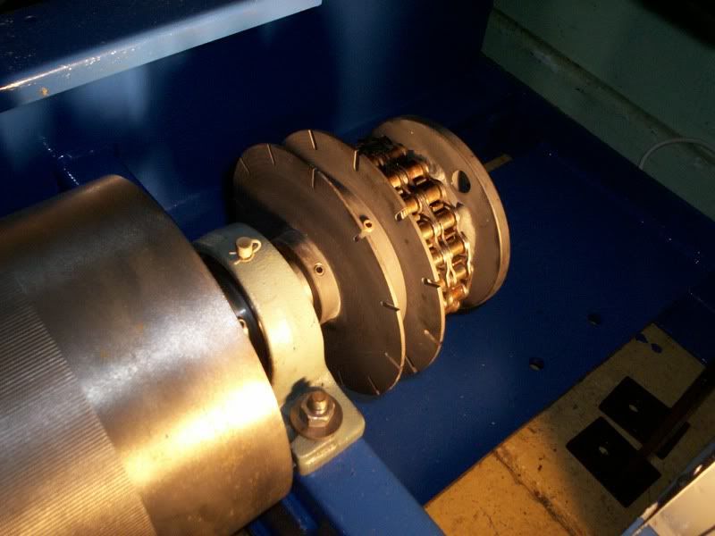
The retarder has been removed in this picture, but it normally sirs at the right hand side, bolted to the chain coupler via the flange.
I have never seen anything quite like this before, and it is highly unlikely any commercial dyno software would accept this type of digital torque input signal. But it is a brilliant idea, just two already digital input signals to a computer, and you get rpm plus torque measurement, already as noise free high level digital signals. No noisy, drifty, low level analog signals from a strain gauge. The retarder is bolted solid to the frame, and no need for it to rock and vibrate on extra bearings, and it is all so SIMPLE.
But it does illustrate how something a bit unusual may cause huge problems when trying to interface it to some incompatible hardware or incompatible commercial software.
For myself all I had to do was write some software to suit the mechanical parts I already had. For me, that was a far easier and a much neater solution than to start cutting and welding the dyno frame.
That is undoubtedly a very good thing, and will suit many people just fine, but it may also end up being just a little bit beyond the budget of others.
Another factor, is that a few people may already have some sort of salvaged dyno hardware, or plan to fabricate something themselves completely from scratch. The Land and Sea system may require some custom electronics or tricky interfacing to get something a bit unusual working.
An example of this is my own dyno. This is a Vane VP930 rolling road, very well built too, but it uses a rather unique method to measure the torque.
There is a hollow shaft through one roller, and a long torsion bar through the middle to drive the eddy current retarder. There are two twelve tooth slotted optical discs, one connected to the roller and the other to the retarder drive. These rotate together, except increasing torque twists the torsion bar and creates relative motion between the two rotating discs.
The retarder has been removed in this picture, but it normally sirs at the right hand side, bolted to the chain coupler via the flange.
I have never seen anything quite like this before, and it is highly unlikely any commercial dyno software would accept this type of digital torque input signal. But it is a brilliant idea, just two already digital input signals to a computer, and you get rpm plus torque measurement, already as noise free high level digital signals. No noisy, drifty, low level analog signals from a strain gauge. The retarder is bolted solid to the frame, and no need for it to rock and vibrate on extra bearings, and it is all so SIMPLE.
But it does illustrate how something a bit unusual may cause huge problems when trying to interface it to some incompatible hardware or incompatible commercial software.
For myself all I had to do was write some software to suit the mechanical parts I already had. For me, that was a far easier and a much neater solution than to start cutting and welding the dyno frame.
Also known as the infamous "Warpspeed" on some other Forums.
- Tony
- Posts: 824
- Joined: Sat Dec 03, 2005 12:34 pm
- Location: Melbourne, Australia
![]() by Tony » Sun Jan 06, 2008 5:07 pm
by Tony » Sun Jan 06, 2008 5:07 pm
Calibration is certainly the tricky part with this system, it is a matter of measuring how much the torsion bar twists for a given amount of torque. So far I have tried two different methods to get some firm numbers.
First thing was to very carefully measure the physical dimensions of the torsion bar. I measured the diameter in ten places and averaged the diameter. I then used the torsion bar formula from an engineering reference book to calculate the angular twist versus applied torque.
Next I mounted the whole roller in the lathe. The drum was locked solid by winding some heavy steel towing cable around the drum many times, and securing the end to the lathe bed. Both the retarder drive flange and a very long (balanced) horizontal torque arm were bolted to the lathe face plate.
I then hung various barbell weights to the torque arm and measured the relative movement between the two slotted discs with calipers. Both theoretical and measured numbers agreed with 4%. difference.
I will do this again but not in the lathe next time, but with everything finally mounted back in the dyno frame. It was easier for me to do it in the lathe because everything was disassembled. I also just assumed that the crappy cheap rough cast iron barbell weights actually weighed what was cast into the weights. These barbell castings are lumpy and horrible looking, I just assumed eight of them might average out fairly close to their rated weights, supreme optimism maybe ?
Before I do all this again, I will get these weights weighed at several different places, and try to get some accurate numbers. I suspect my 4% error is mainly due to the test weights being inaccurate. Still, it worked out close enough to make an encouraging start.
There is also some cunning in the software. There are twelve slots, and these may not be exactly even around each disc, although they were probably originally production milled with a proper indexing head ?? But there may still be small mechanical errors. So what I have done is calculate the rpm and torque for every tooth, and take the average of every twelve readings. It does not then matter if the teeth are all over the place, because if you average for one complete revolution, any individual lumpy readings will be corrected.
I plan to use this dyno for engine tuning, as long as the torque reading is fast, sensitive and repeatable, I could not care less if it is out by a few percent. But I think with a bit more thought patience and care, I can get very very close with this. Once I have a suitable calibration number entered into the software I cannot see how it can change. The zero torque point might drift slightly, but the torsion bar stiffness should not.
The software just measures very small time increments, and averaging a great many readings giving even higher theoretical resolution. I expect it should work quite well. But right now the Telma retarder is out of the dyno, and I am messing around experimenting with different ways to control the dc drive current through the retarder windings.
Also known as the infamous "Warpspeed" on some other Forums.
- Tony
- Posts: 824
- Joined: Sat Dec 03, 2005 12:34 pm
- Location: Melbourne, Australia
![]() by 1960flh » Sun Jan 06, 2008 9:08 pm
by 1960flh » Sun Jan 06, 2008 9:08 pm
[color=#000000]Tony,
This is a very neat and simple concept instead of a strain gage, as long as the torsion bar is not over loaded and damaged. For a simple periodic calibration test have you thought of using a good digital or dial torque wrench to get figures at say 50, 100,150,200,250
This is a very neat and simple concept instead of a strain gage, as long as the torsion bar is not over loaded and damaged. For a simple periodic calibration test have you thought of using a good digital or dial torque wrench to get figures at say 50, 100,150,200,250
HP = Torque x RPM / 5252
- 1960flh
- Posts: 65
- Joined: Mon Dec 04, 2006 12:50 am
- Location: Maryland
![]() by Tony » Sun Jan 06, 2008 10:03 pm
by Tony » Sun Jan 06, 2008 10:03 pm
Rick, any spring can be overladed beyond it's elastic limit and permanently deform. Even a very expensive strain gauge cell will do that.
When I first had the roller mounted in the lathe, the very first thing I tried was placing the lathe in it's lowest gear (15.75 : 1) and using a torque wrench on the the lathe gearbox input shaft. There is a giant nut there anyway, so that was very easy. I found that sliding friction in the two stages of helical cut gears, created far too much uncertainty for any accurate and repeatable reading. And anyhow, I had no real way of knowing if my torque wrench is even very accurate. As it turned out these initial attempts were at least 20% out and pretty useless
The retarder itself is fairly small, and rated to 500 Ft/lb at 4,500 max rpm (428 Hp) So I did all my testing at 500 Ft/lb. That twists the torsion bar just under half a tooth or very approximately 12.5 degrees. Rear axles and antiroll bars normally twist far more than that.
The measurement radius is unimportant. For speed measurement it is the number of pulses per unit time, and that does not change with radius. I will get twelve flashes per roller revolution no matter what.
For torque measurement the situation is similar, in that it is time delay per slot being measured, which is really the same thing.
What I expect will screw things up most, is vibration which will produce jitter on the waveforms. But by taking and averaging hundreds of readings I should be able to get a good solid non fluctuating output number of sufficient resolution. This is really all in the software, and it is fairly easy to change things around for best possible results.
While all this is a bit of trouble to get going initially, it should prove to be very simple and reliable with very little to go wrong. I am told these dynos are mechanically bullet proof, but the original electronics were rather failure prone. That is why I planned to use it just as is, and not modifying it at all mechanically.
Also known as the infamous "Warpspeed" on some other Forums.
- Tony
- Posts: 824
- Joined: Sat Dec 03, 2005 12:34 pm
- Location: Melbourne, Australia
![]() by 1960flh » Mon Jan 07, 2008 9:24 am
by 1960flh » Mon Jan 07, 2008 9:24 am
Tony,
So are you actually measuring the pulse time delay between the Fixed disk (RPM) to the moving disk (Torsion Bar), then converting this to Degrees of rotation of the torsion bar???
Rick
So are you actually measuring the pulse time delay between the Fixed disk (RPM) to the moving disk (Torsion Bar), then converting this to Degrees of rotation of the torsion bar???
Rick
HP = Torque x RPM / 5252
- 1960flh
- Posts: 65
- Joined: Mon Dec 04, 2006 12:50 am
- Location: Maryland
![]() by Tony » Mon Jan 07, 2008 4:38 pm
by Tony » Mon Jan 07, 2008 4:38 pm
The microcontroller I am using has two of what are called "input capture" inputs. Whenever an incoming pulse edge arrives, the microcontroller logs and records the exact time of arrival by reading a very fast internal clock. Time resolution being in half microseconds.
The time of arrival of each previous pulse from the roller chopper disc, is subtracted from the time of arrival of the most recent pulse. The result is a fairly large number measuring the number of half microseconds between incoming pulses. From this it is quite straightforward to calculate instantaneous rpm twelve times per roller revolution.
A similar recording of the exact arrival time of the pulse from the torque reading chopper disc is made. The earlier previous roller speed reading time is subtracted from the torque disc arrival time, giving another fairly large number.
So we have measured the tooth to tooth time period, and the delay time from the far end of the torsion bar. Both these numbers go up and down together with dyno speed, but by dividing the delay into the total tooth to tooth period, we can get a torsion bar angular displacement reference number that is independent of roller speed. Call this the "raw" torque number.
For example, this raw torque number might be 0% if it arrived exactly coincident with a previous speed tooth, and 100% if it arrived exactly coincident with the most recent speed tooth. In practice only a small part of this range is used. You certainly would not want to twist the torsion bar by a whole tooth.
This raw torque reading needs to first be zero corrected. When you assembled the dyno, the torque chopper disc will have been mechanically fitted to the shaft to lag slightly behind the speed chopper disc by some probably unknown amount at zero torque. The raw torque reading might be telling you 13.24 % (or something) of a tooth angular displacement with zero torque being transmitted. By subtracting 13.24% (or whatever), the raw torque output reading can first be zeroed.
The next stage is to multiply this now zero corrected raw torque number by a calibration figure, to produce a torque reading in the units of your choice.
Once you have twelve rpm readings, and twelve corrected torque readings per roller revolution, the rest is fairly straightforward number crunching.
Also known as the infamous "Warpspeed" on some other Forums.
- Tony
- Posts: 824
- Joined: Sat Dec 03, 2005 12:34 pm
- Location: Melbourne, Australia
![]() by CraigAPD » Sat Jan 12, 2008 5:28 am
by CraigAPD » Sat Jan 12, 2008 5:28 am
Ok, something related to the control side of a dyno ive been trying to get my head around....
In order to measure the maximum torque output of an engine for a given engine speed, the retarder must apply an equal (and obviously opposite) "braking" force on the engine. This means that in order to get a TRUE MAXIMUM torque measurment, the engine must be instantaneously on the verge of stalling?? IE It has to be equal loading to the output, otherwise if its less than the torque exerted by the engine, the resultant movement of the cradle wont be maximised...it wil be less than it COULD be....i.e not measuring full torque.
E.g an engine produces 200N.m. Therefore the retarder must apply an equal force in order to measure actual torque? any less we will measure say 175N.m, and any more and the engine will be made to stall??
Is this correct logic, or am I missing something?!
- CraigAPD
- Posts: 24
- Joined: Fri Jan 04, 2008 2:44 pm
- Location: England
![]() by Tony » Sat Jan 12, 2008 6:59 am
by Tony » Sat Jan 12, 2008 6:59 am
No not stalling, just running at a constant speed wide open throttle fully loaded.
What happens is you tell the dyno control system to hold the engine at say exactly 4,000 rpm. So you open the throttle a bit and it accelerates up from normal idle speed to 4,000 rpm with little or no resistance from the dyno.
As soon as it reaches the required speed, the dyno starts to very quickly increase it's load to hold that speed exactly. If it goes to 4,001 rpm the dyno resistance increases, if it falls to 3,999 the dyno resistance decreases. So the dyno control system controls the speed by altering the load, and tries to balance exactly the torque that the engine is producing.
What the dyno then measures is the torque produced and absorbed at exactly 4,000 rpm with the throttle held wide pen. If you then close the throttle, the engine slows back down to idle speed.
The challenge is to build a control system that acts very quickly and positively, without any speed overshoot or speed hunting. This is made more difficult because of the fairly sluggish and often non linear response of most types of retarder.
Also known as the infamous "Warpspeed" on some other Forums.
- Tony
- Posts: 824
- Joined: Sat Dec 03, 2005 12:34 pm
- Location: Melbourne, Australia
40 posts
• Page 2 of 3 • 1, 2, 3
Who is online
Users browsing this forum: No registered users and 1 guest