
ahhh of course!!
It slipped my mind that they target speed...i was thinking about load too much!
So carrying on from your control module, what will you do in terms of electronics to target engine speed, then to correct the pulse width to alter load?
Pulse width modulated power control
40 posts
• Page 3 of 3 • 1, 2, 3
![]() by Tony » Sat Jan 12, 2008 4:59 pm
by Tony » Sat Jan 12, 2008 4:59 pm
My first challenge is to build a system that is able to control the massive amount of stored magnetic energy in the Telma windings, so that the retarder will respond as fast as possible, respond as nearly the same for changes in both directions, and respond the same at both high and low power levels. And that ain't easy.
Once I have sorted out the retarder so it is reasonably well behaved, I can build a speed control feedback loop. These are known as a PID controller. How much error can be fed back, and how fast an error can be corrected is determined by the tuning of this closed loop. Too much, or too fast a correction leads to instability, too little, or too slow, leads to very sloppy control characteristics.
Once that is all done, I should be able to set an exact target rpm, and the dyno should very rapidly come up to that set rpm and hold it rock solid, without any hesitation or wavering of speed.
If I can get it to do that, then the next step is to get it to do sweep testing. Instead of a fixed dyno target speed, the set target speed is moved or swept at the required acceleration rate, while recording data.
But to achieve that final goal, first the closed loop speed control system needs to be made as perfect as I can make it. If the dyno speed wobbles all over the place out of control, sweep testing is meaningless, as there will be no repeatability.
Also known as the infamous "Warpspeed" on some other Forums.
- Tony
- Posts: 824
- Joined: Sat Dec 03, 2005 12:34 pm
- Location: Melbourne, Australia
![]() by CraigAPD » Sat Jan 12, 2008 8:22 pm
by CraigAPD » Sat Jan 12, 2008 8:22 pm
cheers for the reply mate....very helpful!
What are the variables involved when you talk about "tuning the closed loop"? I take it its certain values in the hardware arrangment (sorry if my questions seam daft, but i havnt much experience with electronics).
I still think im going to opt for the easy option and buy the required hardware from Land and Sea LOL
- CraigAPD
- Posts: 24
- Joined: Fri Jan 04, 2008 2:44 pm
- Location: England
![]() by Tony » Sat Jan 12, 2008 9:01 pm
by Tony » Sat Jan 12, 2008 9:01 pm
Ah ! that is the sixty four dollar question. Tuning control loops for best performance is a whole subject in itself:
For what we are doing, only a proportional integral controller is required, but they are still called PID, even though there will be no derivative action.
Tuning involves setting the proportional gain, and setting the integral time constant to suit the application. The secret of success is to remove any non linearities from what you are attempting to control, so that it behaves predictably.
This applies to controlling the water level inside a water brake, just as much as controlling the current flow through an eddy current retarder. The hardware is rather different, but the control problem is actually quite similar.
I don't personally think a water brake is the easy option, the control characteristics are going to be far more complex. If you are going to buy the whole lot from Land and Sea, including the entire control system and software, that would be best.
If it is just the bare water brake, there are going to be some rather interesting challenges ahead controlling it.
Also known as the infamous "Warpspeed" on some other Forums.
- Tony
- Posts: 824
- Joined: Sat Dec 03, 2005 12:34 pm
- Location: Melbourne, Australia
![]() by gofaster » Sun Jan 13, 2008 3:44 am
by gofaster » Sun Jan 13, 2008 3:44 am
I'm using a Land and Sea Eddy Current Motorcycle / ATV Chassis Dyno, and it does a fine job of holding engines at chosen road speeds for Fuel Injection and carburetor tuning. At first I balked at the price, but I had experience on SF and DJ dynos in the past, and I feel that the Land & Sea unit is a cut above the others.
I originally started talking to Land & Sea because I had an opportunity to pick up a Stuska water brake that I wanted to couple with an inertia roller. They can set you up with everything you need to make everything electronically controlled.
Anyhow, the demand for FI tuning here is great enough that I felt time was more important than money, so I took the easier route and bought a complete dyno from them.
Edited By gofaster on 1200210345
Jim
- gofaster
- Posts: 237
- Joined: Fri Jul 01, 2005 6:39 pm
- Location: Indiana
![]() by CraigAPD » Sun Jan 13, 2008 7:11 am
by CraigAPD » Sun Jan 13, 2008 7:11 am
Sounds good. How have you found their after-sales technical support?
I have a friend here in the UK who has built a twin roll chassis dyno from scratch, using a L&S 13" water-brake and all the required hardware/software/DaQ etc. Its a very effective set-up, and he says the technical support from them alone is worth buying from them, let alone the functionality of their products.
Tony, how far off having a finnished/usable set-up are you?
- CraigAPD
- Posts: 24
- Joined: Fri Jan 04, 2008 2:44 pm
- Location: England
![]() by Tony » Sun Jan 13, 2008 5:17 pm
by Tony » Sun Jan 13, 2008 5:17 pm
Difficult to estimate, as this is a part time hobby project with no deadline.
I have spent many weeks on this retarder control problem, but now have something fairly simple and also extremely unique that works pretty well.
This will all be presented here, once I am completely happy with it. Right now I keep thinking of new ideas to try, or ways to make it simpler or perform better. A lot of effort is going into making something that others can copy with minimum cost and drama.
My biggest problem with this dyno will be noise, as I have fussy snobby neighbors close by, so I will have to do a lot of work with noise suppression before I can really rip into some testing. I am already known as the bad boy on the block.
Also known as the infamous "Warpspeed" on some other Forums.
- Tony
- Posts: 824
- Joined: Sat Dec 03, 2005 12:34 pm
- Location: Melbourne, Australia
![]() by Tony » Sat Jan 19, 2008 12:19 am
by Tony » Sat Jan 19, 2008 12:19 am
O/k I now have something pretty well figured out, which now works well as a prototype in the electronics lab, but have yet to build it up properly in it's final form and actually run it on my dyno.
What follows is some basic philosophy and the reasons why it has been built the way it has. I have tried to keep it simple and in a form that others can copy or at least perhaps gain some ideas from. Circuit diagrams and parts lists will come later.
The first requirement is some type of digital pulsed output from the dyno shaft to measure shaft speed. How many pulses there are per revolution is not extremely critical, but more pulses per revolution will be better. There are many possible ways to go about doing this, but most modern dynos will already have something suitable fitted.
If you are starting completely from scratch, a slotted disc with optical pickup, or some type of magnetic pickup are the usual method. You can fabricate all this yourself or perhaps adapt a salvaged electronic ignition distributor or cam angle sensor to the task.
Some older style dynos used a tacho generator, which is just like a bicycle dynamo, the faster it goes the higher the output voltage. Not very good, so get rid of it, and fit a proper digital pulse pickup of some type.
So now we have a nice clean train of digital pulses, and we can work out the maximum and minimum output frequency from the maximum and minimum dyno operating rpm, and the number of slots (or teeth) easily enough.
The next requirement is an adjustable oscillator which we can set to the required dyno target running speed. This could take several forms.
The simplest is just a small box with a knob and internal oscillator chip that you adjust in the car to set roller speed for engine tuning. Or it could be something a lot more sophisticated generated by a fancy software program for doing automated sweep tests. But whatever it is, it just produces a specific set output frequency, which is the input command for our proposed closed loop dyno speed control system.
There are several advantages to directly locking the dyno to a reference frequency instead of some adjustable dc control voltage. Speed locking can be very precise, and it is also possible to exactly speed lock two separate dynos, as with four wheel drive. Exact precise digital frequencies are also very easy to generate and measure with computers and software. Direct digital speed control of our dyno opens up a lot of possibilities.
But it could also just as easily be a very simple low cost plastic box with a speed knob. At least, that is all I plan to have to start with.
So now we have our oscillator which determines the required target running speed as one digital signal, and the pulse output from our shaft which is what the dyno is actually doing as a second digital signal.
These two signals go into a low cost and rather clever digital frequency/phase comparator chip. (CD4046)
This chip has a few features, but we are only interested in the phase comparator part of it. The phase comparator produces an output capable of exactly phase locking the slots in the disc to the positive transitions of the maser oscillator signal. If the slots lead or lag by even a small fraction, this chip creates suitably narrow correction pulses to speed up or slow down the dyno.
If two separate dynos are being controlled together from one oscillator, the front and rear wheel rollers should become virtually electrically locked solid together with this system. But for just a single dyno, it potentially offers very sensitive and solid locking of dyno speed.
The output from our frequency/phase detector chip is a digital on/off signal which swings violently up and down, and produces some very rapid and nervous small corrections to the most minute errors detected at each and every every slot.
In any feedback system how much correction is applied, and how fast a correction is applied is extremely important.
Imagine trying to steer a car down the road that had no steering wheel, just a switch. You could select either full left lock, or full right lock, and it goes hard from lock to lock in a tenth of a second with no center ahead steering position. It would be undrivable even at walking speed.
So we need something to manage the very fast sensitive and violent "lock to lock" on/off digital corrections coming out of our CD4046 phase detector chip to control how much and how fast the dc supply power is fed into to our dyno power absorber, as is is varied up and down in mechanical load.
This is known as a PID controller. (proportional, integral, derivative) It is really just two resistors and a capacitor, and the values of these three components must be suitably adjusted (tuned) to give suitable control characteristics to the whole closed loop dyno speed control system. More on this later.
But what comes out of the PID controller is a varying dc control voltage that directly adjusts the power going into an eddy current absorber (or the water flow into a water brake). It is the tuning of this PID controller that determines how fast and stable the correction of any detected dyno speed errors will be.
This PID controller output voltage is what adjusts the amount of mechanical resistance of the dyno to engine torque, and ultimately holds the dyno to it's correct set running speed.
All the above is fairly straightforward control circuitry, but controlling the massive stored energy in a Telma eddy current retarder is not as simple as it first appears. And that is the next problem to tackle.
Also known as the infamous "Warpspeed" on some other Forums.
- Tony
- Posts: 824
- Joined: Sat Dec 03, 2005 12:34 pm
- Location: Melbourne, Australia
![]() by Tony » Sun Feb 10, 2008 8:30 pm
by Tony » Sun Feb 10, 2008 8:30 pm
Sorry for the long pause, but actually getting started on the physical construction part of this project has taken a while.
As this will have some fairly lethal voltages inside, my first problem was what the heck to build it into ? But I managed to find a nice neat metal enclosure on e-bay at a friendly price.
Any resemblance to a single drawer filing cabinet is purely coincidental !
Although really a bit large for what is required, it is certainly a very practical solution to the enclosure problem. This is a very old filing cabinet with a flat front. Most more modern filing cabinets have a large recessed handle which takes up a lot of space, and is not quite so convenient. These recessed handles cannot really be removed because it just leaves a huge hole.
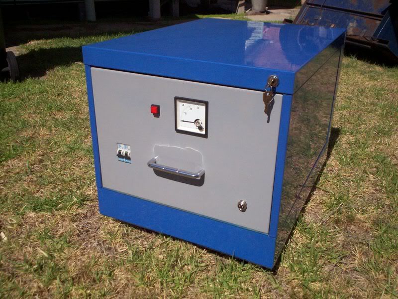
At the moment the insides are completely empty, but I need to start somewhere, and this is the beginning.
The 30 amp meter will show the dc current through the retarder windings, the red lamp ac mains power. The five pin socket on the lower right will be for the in car dyno hand controller. Two circuit breakers, one to supply the main dyno electronics, and the other to power the retarder cooling blower. The idea is so that I can run the retarder cooling blower for a time after everything else has been switched off.
It is blue, because the rest of the dyno frame has been painted the same blue. Not seen in the picture, but four swivel casters have been fitted underneath to triangular gusset plates pop riveted into the corners of the base.
As this will have some fairly lethal voltages inside, my first problem was what the heck to build it into ? But I managed to find a nice neat metal enclosure on e-bay at a friendly price.
Any resemblance to a single drawer filing cabinet is purely coincidental !
Although really a bit large for what is required, it is certainly a very practical solution to the enclosure problem. This is a very old filing cabinet with a flat front. Most more modern filing cabinets have a large recessed handle which takes up a lot of space, and is not quite so convenient. These recessed handles cannot really be removed because it just leaves a huge hole.
At the moment the insides are completely empty, but I need to start somewhere, and this is the beginning.
The 30 amp meter will show the dc current through the retarder windings, the red lamp ac mains power. The five pin socket on the lower right will be for the in car dyno hand controller. Two circuit breakers, one to supply the main dyno electronics, and the other to power the retarder cooling blower. The idea is so that I can run the retarder cooling blower for a time after everything else has been switched off.
It is blue, because the rest of the dyno frame has been painted the same blue. Not seen in the picture, but four swivel casters have been fitted underneath to triangular gusset plates pop riveted into the corners of the base.
Also known as the infamous "Warpspeed" on some other Forums.
- Tony
- Posts: 824
- Joined: Sat Dec 03, 2005 12:34 pm
- Location: Melbourne, Australia
![]() by FPV_GTp » Sun Nov 09, 2008 6:45 pm
by FPV_GTp » Sun Nov 09, 2008 6:45 pm
Very interesting read guys , Tony you certainly contribute tpo the forum and nice work might I say/
Tony any further updates on you dyno venture.
Is there a thread in this forum or any other forum of someone constructing/fabricating a complete waterbrake absorber on a DIY level ? , could you please PM it to me or list it in this thread.
cheers
Tony any further updates on you dyno venture.
Is there a thread in this forum or any other forum of someone constructing/fabricating a complete waterbrake absorber on a DIY level ? , could you please PM it to me or list it in this thread.
cheers
Ford Sale - ( Melb , Aust ) - Engine Dynamometer Heenan & Froude G490EH 1,500Bhp@15,000rpm - Ship World Wide
- FPV_GTp
- Posts: 90
- Joined: Thu Oct 02, 2008 6:04 am
40 posts
• Page 3 of 3 • 1, 2, 3
Who is online
Users browsing this forum: No registered users and 1 guest