
Hello I ask a little help for build a circuit automatic speed regulator for the engines of my flowbench I have already modules Kemo M 028 power control 2600 W 230 V and optional modules Kemo M 150 DC converter and pulse these modules replace the manual knobs to operate the module M 150 requires a command signal 1 to 5 V or TLL impuls have you an idea for the circuit design that can provide a signal to the M 150 depending on the pressure and have permanently 10 25 or 28 inch suction.
thank you
motor controller
10 posts
• Page 1 of 1
![]() by 49-1183904562 » Sat May 24, 2008 6:18 pm
by 49-1183904562 » Sat May 24, 2008 6:18 pm
CRE;
There is no easy answer to this problem but you do have part of the solution and that is a motor speed controller that accepts voltage input to vary motor speed.
The solution would look like this, first you must be able to read depression electronically as many of the other post in this section are searching for an answer to. Second you will need to process the information (Current Depression) in a program say C or VB (Visual Basic) or VBA, or some other programming language. Last you must be able to perform Digital to Analog output. The basic logic is as follows.
I/E
Do loop until
If depression > 28 then
Lower output voltage by x
Else if depression <28
Increase voltage by x
Else if depression = 28
Voltage = voltage
End if
If stop = Yes then
End program
End if
Loop
I would look at the Dataq product as it has both A to D And D To A to perform the needed input output and also will interface easily with VB or VBA through say an Excel Spreadsheet.
Hope this helps
Rick
- 49-1183904562
![]() by Tony » Sat May 24, 2008 8:19 pm
by Tony » Sat May 24, 2008 8:19 pm
Rick is spot on.
You already have the motor speed control that requires a dc input voltage.
Next you will need a pressure measurement manometer that outputs a dc voltage proportional to pressure.
The third requirement are the "brains" or the "control system" to correct motor speed to hold the required constant pressure.
This can be done two different ways. One alternative is using software, the other a fairly simple PID controller implemented in electronic hardware, using a handful of very low cost electronic parts.
Some people will feel more comfortable with the software approach, but myself, I prefer to spend less than five dollars on parts, and build a small circuit.
The circuit itself is very simple, but to get it to work properly requires two tuning adjustments. This involves selecting resistor and capacitor values to suit the rest of the system.
Ricks software also requires tuning, in that the "x" term will need to be determined experimentally. Too large and the pressure will hunt, too small and response to correct will be sluggish.
Tuning the analog circuit involves first making the time constant very long, and the gain very low. That is make R1 and C1 very large and R2 very small. The circuit will correct and hold the set pressure, but the correction time will be unreasonably long, and it will probably take ages to settle at the correct pressure.
Start increasing R2 in steps to increase the gain. Each step should be maybe a doubling of the previous resistor value. Not much will appear to happen, until at some point the circuit becomes unstable. Motor speed will hunt up and down, and it will go crazy. Find a value of R2 where it is just borderline unstable, then drop back to half or a quarter of that borderline resistance, to ensure gain stability. Don't bother trying to fine tune this, factors of two are plenty close enough.
Next start reducing C1 in value to make the response faster. Keep reducing C1 until the circuit again goes nuts and motor speed becomes unstable. Once the borderline stability point has been found, increase C1 by fifty percent or maybe a bit more. Again not critical.
Once you have tuned the circuit, it will respond quickly and cleanly to changes in the pressure set point, and it will hold constant pressure.
If you Google PID loop tuning, you can learn much more, but if you follow the above tuning procedure there should be no trouble in finding some suitable resistor and capacitor values to suit your particular blower and manometer characteristics.
When you start out, the circuit may be unstable, and it is not at all obvious if it is the gain or the time constant that is the problem. But once stable, you can sneak up on both to optimize the response.
Gain can be more than one (R2>R1) or less than one (R1>R2) by factors of a hundred or more. It all depends on how sensitive your manometer, and how powerful your blower motor. The more hairy your setup the less gain it will take before instability sets in.
Likewise the time constant depends on motor inertia, and air volumes, anything that is time related. I cannot really even begin to suggest ideal component values to start with , but something really conservative like R1 = 1Meg and R2 = 10K, sets the gain to 1/100 (1 volt change in gives 10mV change out or gain x 0.01)
And C1 = 22uF bipolar (with R1 set to 1meg) time constant = 22 seconds
These values will almost certainly be way off what you finally end up with, but you need to start somewhere.
* Please note that the capacitor must be a non polarized type. Bipolar electrolytic capacitors are o/k, but ordinary polarized electrolytics marked with a + and - are not suitable.
* More detail on PID loop tuning, either software or hardware, the principle is exactly the same.
Also known as the infamous "Warpspeed" on some other Forums.
- Tony
- Posts: 824
- Joined: Sat Dec 03, 2005 12:34 pm
- Location: Melbourne, Australia
![]() by Tony » Sun May 25, 2008 7:38 pm
by Tony » Sun May 25, 2008 7:38 pm
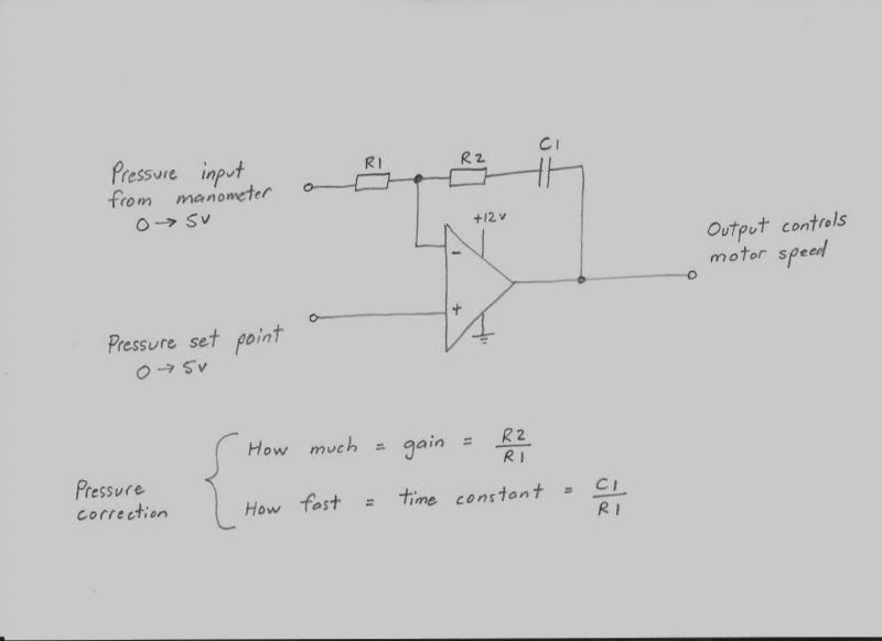
A nice low cost readily available chip would be an LM358. The resistors can be metal film types, and the capacitor any non polarized type. A battery or dc plug pack would be ideal to power this circuit up initially.
I have shown the input voltage from the manometer and the pressure set point control as being 0 to +5v range, but they could really cover any other convenient voltage range.
Whatever dc voltage your manometer generates at the required test pressure, the pressure control knob needs to be able to output the same identical set point voltage.
The supply voltage does not need to be exactly 12v, anything between 12v and 24v dc will work fine.
You could start out by trying component values in steps of 10:1 to narrow down the range fairly quickly.
Say R1 = 1 Meg
R2 = 10K, or 100K, or 1 Meg, or 10 Meg
C1 = 22uF, or 2.2uF or 220nF, or 22nF
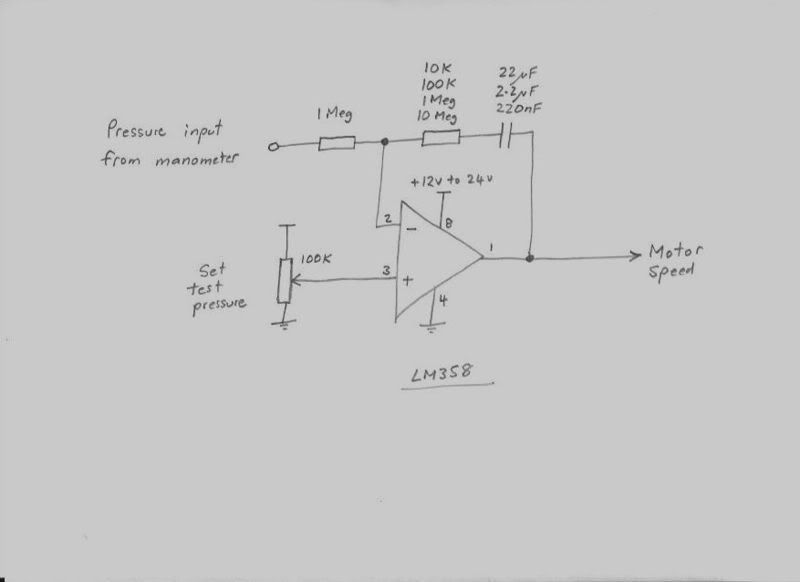
The left hand side of the range is very conservative, and the right hand side steps to much more radical values, and instability for sure. But see how far you can go before it becomes wildly unstable, then go back a step.
Then you can try changing things in smaller steps of 2:1 to narrow it down further.
Instability will show up as violent surging in motor speed, or hunting, and you will hear this very clearly. What you want is to be able to move the test pressure control knob up and down, and the test pressure will follow fairly rapidly and then sit there rock solid. It should also quickly adapt to large sudden flow changes without any instability once it is tuned properly.
It may be stable at some combinations of flow and pressure, and become increasingly unstable at different flows and pressures. In this case do your testing at the most unstable part of the range, and tune it there so it becomes stable.
The reason for this has to do with the characteristics of the blower. At some places in the control range, a small change in blower control voltage will cause a larger change in output pressure. The blower might be said to be more sensitive, and have more "gain" at that operating point. To prevent instability, the gain inside the controller will need to be reduced so total gain around the whole loop can never be high enough to cause instability.
That is the only real problem with these PID controllers, non linearity in what is being controlled can sometimes make tuning more difficult than it should be.
I have shown the input voltage from the manometer and the pressure set point control as being 0 to +5v range, but they could really cover any other convenient voltage range.
Whatever dc voltage your manometer generates at the required test pressure, the pressure control knob needs to be able to output the same identical set point voltage.
The supply voltage does not need to be exactly 12v, anything between 12v and 24v dc will work fine.
You could start out by trying component values in steps of 10:1 to narrow down the range fairly quickly.
Say R1 = 1 Meg
R2 = 10K, or 100K, or 1 Meg, or 10 Meg
C1 = 22uF, or 2.2uF or 220nF, or 22nF
The left hand side of the range is very conservative, and the right hand side steps to much more radical values, and instability for sure. But see how far you can go before it becomes wildly unstable, then go back a step.
Then you can try changing things in smaller steps of 2:1 to narrow it down further.
Instability will show up as violent surging in motor speed, or hunting, and you will hear this very clearly. What you want is to be able to move the test pressure control knob up and down, and the test pressure will follow fairly rapidly and then sit there rock solid. It should also quickly adapt to large sudden flow changes without any instability once it is tuned properly.
It may be stable at some combinations of flow and pressure, and become increasingly unstable at different flows and pressures. In this case do your testing at the most unstable part of the range, and tune it there so it becomes stable.
The reason for this has to do with the characteristics of the blower. At some places in the control range, a small change in blower control voltage will cause a larger change in output pressure. The blower might be said to be more sensitive, and have more "gain" at that operating point. To prevent instability, the gain inside the controller will need to be reduced so total gain around the whole loop can never be high enough to cause instability.
That is the only real problem with these PID controllers, non linearity in what is being controlled can sometimes make tuning more difficult than it should be.
Also known as the infamous "Warpspeed" on some other Forums.
- Tony
- Posts: 824
- Joined: Sat Dec 03, 2005 12:34 pm
- Location: Melbourne, Australia
![]() by 115-1172523331 » Sun May 25, 2008 8:43 pm
by 115-1172523331 » Sun May 25, 2008 8:43 pm
Ok, Dumb question(s) time!
First, I assume the pressure transducers (or similar) we were talking about in the Digital display thread would be the input device to the comparator chip. Is this right?
Second, Does this circuit replace the HF motor controller we found for Bruce's plans? The output wires to the motor input side and the voltage goes +/- as dictated by the comparator? Motor ground is unchanged?
Third, What is the pressure "setting" input at the lower left of the last diagram? Again, I am assuming that it is where you tell the device you want 10 in WC, 28 in WC, or whatever, but physically, what is it?
Still trying to learn! -- Doug
- 115-1172523331
![]() by Tony » Sun May 25, 2008 9:23 pm
by Tony » Sun May 25, 2008 9:23 pm
Doug, first requirement is to be able to control the blower motor speed with a fully isolated dc control voltage. This could be with a a variable frequency drive, or something like the Kemo power control modules that cre is using, or something very similar.
A basic motor speed controller such as a Harbor freight router controller that just has a control knob is NOT going to work.
There need to be two input terminals fully isolated from the mains supply instead of the control knob. Into these two terminals you feed a dc control voltage which causes the power to the motor to vary.
Many different ways to achieve that, but none of then are ultra low cost or simple.
The second requirement is something that converts test pressure into a dc output voltage. It could be a commercial pressure manometer (if it has an analog output) or something you build yourself with a pressure transducer and an amplifier. That idea is discussed in more detail on another thread on the Forum.
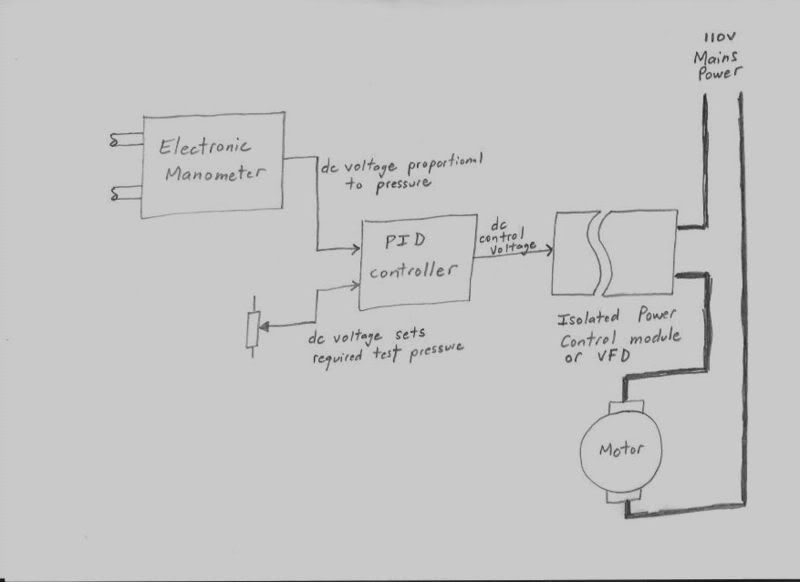
The control system we are discussing here, is what is required to connect these two together, so that you can set the required test pressure (with a knob), and the system will adjust blower speed to reach, and then hold a constant set test pressure automatically.
A basic motor speed controller such as a Harbor freight router controller that just has a control knob is NOT going to work.
There need to be two input terminals fully isolated from the mains supply instead of the control knob. Into these two terminals you feed a dc control voltage which causes the power to the motor to vary.
Many different ways to achieve that, but none of then are ultra low cost or simple.
The second requirement is something that converts test pressure into a dc output voltage. It could be a commercial pressure manometer (if it has an analog output) or something you build yourself with a pressure transducer and an amplifier. That idea is discussed in more detail on another thread on the Forum.
The control system we are discussing here, is what is required to connect these two together, so that you can set the required test pressure (with a knob), and the system will adjust blower speed to reach, and then hold a constant set test pressure automatically.
Also known as the infamous "Warpspeed" on some other Forums.
- Tony
- Posts: 824
- Joined: Sat Dec 03, 2005 12:34 pm
- Location: Melbourne, Australia
![]() by 115-1172523331 » Sun May 25, 2008 11:18 pm
by 115-1172523331 » Sun May 25, 2008 11:18 pm
Thanks Tony, The "Electronic Manometer" I assumed was as we were discussing on the other thread so that part is OK.
From what you are saying, I think I understand that the PID is essentially an automated "hand " that acts on a motor controller which has the same function as the HF controller, but does that job in a somewhat different manner, isolated and automatically. I'll do some research on the Kemo and VFD.
The third part is the "knob" which sets the test pressure. This sounds like it could be something as simple as a power supply with a variable resistor to drop the output to something between 0-5VDC to be compared to the Electronic Manometer output. This would need to be calibrated such that some known voltage would be equal to the output voltage from the EM at the desired pressure(s). Knowing a little about temperature compensation and drift, I'm sure it would not be that simple, but is that concept correct?
I'm back on my basic bench next week so hope to have that running by mid-June and calibrated so I can "worry" about details and improvements. Thanks again, Doug
- 115-1172523331
![]() by Tony » Mon May 26, 2008 12:00 am
by Tony » Mon May 26, 2008 12:00 am
The electronic manometer is exactly as discussed elsewhere.
The PID is the "brain" that decides how much, and how fast to apply any correction to the motor power, to reach and hold a stable test pressure setting.
Think of this as like being in under the shower at home, and adjusting the water temperature.
To get the water temperature exactly right needs a delicate touch. You cannot just wildly spin taps around and expect to reach a steady temperature. The water will likely swing from freezing cold to scalding hot as you get more angry with those taps !!!
But if you very slowly move one tap a little bit at a time, you can eventually get the water temperature just right. Controlling blower speed is exactly like that. You need to control how much correction to apply, and how fast to add in the correction.
Two tuning parameters "how much" and "how fast" to correct any error.
Too little, or too slow will work fine, but then it may take a very long time to reach a stable final exact pressure. Too much, or too fast, you will overshoot and the pressure then starts to swing wildly as it desperately keeps over correcting first one way, then the other.
The PID controller is the "brain" and tuning it, is really telling it how aggressive it can be, in correcting any error, without things going horribly wrong and totally out of control.
The control "knob" is just an adjustable voltage source that comes from a potentiometer. The PID controller attempts to reduce any difference between the required test pressure coming from the "knob" and the actual test pressure measured by the "manometer". When these are both the same, the pressure error will be zero, and the test pressure will be whatever you have set on the "knob".
Any difference between the two causes the controller to start slowly changing the power to the motor. But like your shower, you want this correction to be very gentle and gradual, but not to be so slow it takes forever.
The trick is to just make it aggressive enough to work reasonably fast, without any nervous over correction or instability. It is this ability to "tune" a PID controller that makes it so useful in adjusting all sorts of things automatically.
Also known as the infamous "Warpspeed" on some other Forums.
- Tony
- Posts: 824
- Joined: Sat Dec 03, 2005 12:34 pm
- Location: Melbourne, Australia
10 posts
• Page 1 of 1
Who is online
Users browsing this forum: No registered users and 1 guest