
Opps, sorry about that. I thought you meant the air box. I didn't realize you meant the FP1.
Like Larry said, it connects just like your manometers. You can replace the manometers, or T into them.
PS1 (Pressure Sensor number 1) connects to the point where test pressure is measured. PS2 connects on the high and low pressure side of the measuring orifice. That's it!
Edit: I just uploaded a revised drawing (above) showing the connections for a Flow Performance FP1 electronic flow rate processor to an orifice style bench and to a Pitot tube type bench.
John
The Official Mercdog Flowbench thread - The Official Mercdog Flowbench thread
66 posts
• Page 2 of 5 • 1, 2, 3, 4, 5
![]() by Fkned » Mon Sep 26, 2005 7:00 pm
by Fkned » Mon Sep 26, 2005 7:00 pm
No problem John.I thought my post was alittle unclear and went back to edit when you posted,D'oh.Thanks for the help guy's I think John's going to get a call as soon as the plans show up.Considering the price of the Dwyer components,this is a very atractive product for the home builder. 
- Fkned
- Posts: 8
- Joined: Fri Apr 15, 2005 9:50 pm
- Location: Philly,Pa
![]() by Fkned » Mon Sep 26, 2005 7:02 pm
by Fkned » Mon Sep 26, 2005 7:02 pm
John,will there be a version where all the air fittings are in the back so I can build the FP1 right into the cabinet,like SF does w/the flow com for the 1020.Whoops forget it,I just recalled seeing Larry say you have to reverse the air lines to go from int to exh.
- Fkned
- Posts: 8
- Joined: Fri Apr 15, 2005 9:50 pm
- Location: Philly,Pa
![]() by Mouse » Mon Sep 26, 2005 11:40 pm
by Mouse » Mon Sep 26, 2005 11:40 pm
No plans, but FP is always ready to build custom applications to suit your needs. That is one of the nice things about the FP1 is that it is quite adaptable to changes, additions and reconfiguration with its modular design.
Here is a side view drawing of the vacuum valves I am building for my air box:
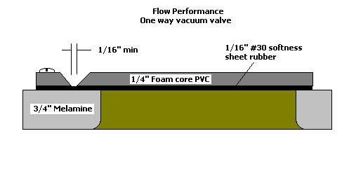
Here is a side view drawing of the vacuum valves I am building for my air box:
- Mouse
- Posts: 308
- Joined: Wed Jan 21, 2004 8:45 pm
![]() by larrycavan » Tue Sep 27, 2005 7:52 am
by larrycavan » Tue Sep 27, 2005 7:52 am
Hi John,
Interesting design with the one way valves. If the valves are actuated by the airflow through the motors, won't the vacuum pressure of a motor sitting below the next one, tend to pull the one way valve above it closed?
In other words if the motors were numbered 1, 2, 3, 4 with 1 being the bottom motor, with 1 and 2 running, won't it be difficult for 3 to lift the valve when you turn it on?
Larry
- larrycavan
- Site Admin
- Posts: 1183
- Joined: Fri Apr 01, 2005 4:40 pm
![]() by mdavidsn » Tue Sep 27, 2005 1:51 pm
by mdavidsn » Tue Sep 27, 2005 1:51 pm
John,
Sorry to jump in here, I'm new to the board and have been following this discussion, what is the purpose and/or benefits of the one-way vacuum valves? What are the advantages of using your receptacle and flow element versus the orfice style shown in your drawing?
Thanks, Mark
Sorry to jump in here, I'm new to the board and have been following this discussion, what is the purpose and/or benefits of the one-way vacuum valves? What are the advantages of using your receptacle and flow element versus the orfice style shown in your drawing?
Thanks, Mark
- mdavidsn
- Posts: 2
- Joined: Tue Sep 27, 2005 10:57 am
- Location: La Grande, Or
![]() by Mouse » Tue Sep 27, 2005 4:55 pm
by Mouse » Tue Sep 27, 2005 4:55 pm
Hi Mark,
Welcome and thanks for your interest.
The purpose of the one way vacuum valves is to be able to turn on only the motors needed to obtain a slightly higher test pressure than needed without losing pressure through the motors that are not turned on. Motors that are not on will not only leak air pressure, but will begin to spin in the opposite direction that they are intended to spin, causing possible damage and current surges when they are started.
When the desired test pressure is slightly exceeded by turning on the needed motors, the correct test pressure can then be obtained by the bleed valve.
The biggest advantage to the patented Flow Performance flow element is that fewer motors are needed to obtain the desired test pressure. This is because there is very little impeadance to air flow within the element. The same cannot be said for an orifice style flow meter. The orifice requires a differential pressure across the orifice and baffling above and below for best performance, both requiring substantialy more air pressure and volume to achieve the desired test pressure on your test piece.
The Flow Performance flow element also has the advantage of being smaller and having a track record of accuracy and repeatability "out of the box".
Another is its portability. I connected an FP element to my truck motor intake one day and mapped my engines MAF sensor. The Flow Performance FE series flow element, the FP1 processor and a Pocket PC make a very portable air flow sensing solution.
There are advantages and disadvantages to both types of flow measuring styles (orifice vs Pitot tube).
Hope this helps
John
- Mouse
- Posts: 308
- Joined: Wed Jan 21, 2004 8:45 pm
![]() by larrycavan » Tue Sep 27, 2005 5:08 pm
by larrycavan » Tue Sep 27, 2005 5:08 pm
Hi John,
Attached is a modified version of your sketch. It's pretty sloppy but the idea is pretty clear. I didn't move the bleed valves. They'll have to be altered too.
The blue lines represent the oneway valves. This should isolate the affect of one to another...then again..????
Larry
Attached is a modified version of your sketch. It's pretty sloppy but the idea is pretty clear. I didn't move the bleed valves. They'll have to be altered too.
The blue lines represent the oneway valves. This should isolate the affect of one to another...then again..????
Larry
- larrycavan
- Site Admin
- Posts: 1183
- Joined: Fri Apr 01, 2005 4:40 pm
![]() by larrycavan » Tue Sep 27, 2005 5:23 pm
by larrycavan » Tue Sep 27, 2005 5:23 pm
John,
I should have explained the idea further. The thought is that each motor chamber volume is small enough that the motor can overcome the pull of the other motors on the one way valve and still allow for the other motors to help to seal the valve when the motor is not in use.
Larry
I should have explained the idea further. The thought is that each motor chamber volume is small enough that the motor can overcome the pull of the other motors on the one way valve and still allow for the other motors to help to seal the valve when the motor is not in use.
Larry
- larrycavan
- Site Admin
- Posts: 1183
- Joined: Fri Apr 01, 2005 4:40 pm
![]() by Thomas Vaught » Tue Sep 27, 2005 6:25 pm
by Thomas Vaught » Tue Sep 27, 2005 6:25 pm
Larry and John,
I built a valve arrangement like Larry has drawn (one way only operation but "staged motors" using Toilet bowl rubber valves for the sealing valves with a small weight on each one). Same "hanging arrangement.
The valves worked great and when you turned off a motor you would hear the valve pop as it shut.
Like I said many years ago. John's sliding deal has a lot of merit and your suggestion on the valve position duplicates some of my early thought.
I still have not figured out a robust sealing deal.
I looked at a split cavity deal where the inlet hole for each "box" was on one level and the vacuum motor was on a staggered different level. You still had the "flat" valve mounting John initially proposed but the air had to go to the right then upward then to the right into the motor. Understand.
Tom V.
- Thomas Vaught
- Posts: 465
- Joined: Fri Feb 18, 2005 5:36 pm
- Location: Michigan
![]() by larrycavan » Tue Sep 27, 2005 7:38 pm
by larrycavan » Tue Sep 27, 2005 7:38 pm
Tom & John,
I'm wondering if an arrangement can be configured to seal the motor intake hole itself.
I was also pondering a spring loaded pawl or detent on the motor shaft that will allow the motor to turn only one direction. In either case, it would need to back completely off when the motor is running to deter noise and possible wear on the shaft.
It's mostly the actuation method that imposes the greatest engineering difficulties. K.I.S.S is always best. That's what's so slick about the oneway valve setup. It utilizes vacuum to perform two functions.
What I don't like is the additional cabinet to employ the system unless you are starting from scratch. I also favor the orifice type bench setup. Not because it's better than a pitot type, it's just a personal preference.
Any ideas on a simple sealing and actuating method that can be applied to an already built orifice bench?
Larry
- larrycavan
- Site Admin
- Posts: 1183
- Joined: Fri Apr 01, 2005 4:40 pm
![]() by Mousehouse1 » Wed Sep 28, 2005 12:04 am
by Mousehouse1 » Wed Sep 28, 2005 12:04 am
Mouse that is an interesting design. Keep us informed on how it turns out.
- Mousehouse1
- Posts: 210
- Joined: Tue Jul 12, 2005 4:27 pm
- Location: Oklahoma City
![]() by Mouse » Wed Sep 28, 2005 10:11 am
by Mouse » Wed Sep 28, 2005 10:11 am
I'll post the results as soon as I get it to a testing stage. I still think my original configuration will work. It is simply a matter of pressure differential on either side of the valve. If 3 motors are on and they can only create 27"wc pressure, then turning on another motor above them should allow air to pass through the valve, unless that motor is not capable of producing 28"wc.
John
John
- Mouse
- Posts: 308
- Joined: Wed Jan 21, 2004 8:45 pm
66 posts
• Page 2 of 5 • 1, 2, 3, 4, 5
Return to Orifice Style bench discussion
Who is online
Users browsing this forum: No registered users and 14 guests