whoa
is that what insanity looks like?
I'll try again.
Tractorsport Flowbench Forum Archive
Archived Flow Bench Forum
http://www.tractorsport.com/forum/
The Official Mercdog Flowbench thread - The Official Mercdog Flowbench thread
Page 1 of 5
Ok you frustrating image, take this;

Several members have a bench that is designed like the mercdog or MSD style bench. I am finishing up my bench and I used the mercdog plans but made some changes. Most of the design is good and will work fine. I was going to use manometers but decided to go with the Flow Performance box and software. I built my own manometers & reservoirs with the exception of buying the incline manometer scale.
Well after reading about the larrycavan I'm wondering if one could fill the area between the original top and the new top with a piece of very open cell foam and get the desired effect. I'm also wondering if the original fixture hole could be made much larger, or even a square, with increased area towards the front of the bench not the back. This would increase the distance between the head fixture and the orifice and the very open cell foam would have a "baffel" effect.
The orifice disc mod larrycavan talks about here seems to be a very logical one especially if the bench is going to be constructed with one orifice disc that will be used in both flow directions. It makes sense (to me too at least) that the flow path on both sides of the orfice should be identical. A 3/4 thick board on each side of the orifice is like a short pipe. I wonder if using a honeycomb straightening section on either side of the orifice plate might help with making flow closer in either direction, since these benchs seem to have a problem matching forward and reverse flow across the orifice. Maybe honeycomb flow straighteners only 3/4 inch away from an orifice is a bad deal, I don't know.
The orifice disc mod larrycavan talks about here seems to be a very logical one especially if the bench is going to be constructed with one orifice disc that will be used in both flow directions. It makes sense (to me too at least) that the flow path on both sides of the orfice should be identical. A 3/4 thick board on each side of the orifice is like a short pipe. I wonder if using a honeycomb straightening section on either side of the orifice plate might help with making flow closer in either direction, since these benchs seem to have a problem matching forward and reverse flow across the orifice. Maybe honeycomb flow straighteners only 3/4 inch away from an orifice is a bad deal, I don't know.
To sum it all up, I'd put it like this.
a- Mercdog or MSD plans are OK...add a top section and baffel.
b - Go FP1 rather than buy manometers.
c - Pay attention to sealing the flowdisk for both directions of flow.
d - Keep number of flowranges to a minimum.
Some guys have built several benches in pursuit of achieving the ideal bench or because it was easier to start over and correct problems that cropped up. Fortunately, their endeavors and achievements are documented here on tractorsport. With a little reading and some careful thought, you can build just one bench and have it contain the design concepts and engineering from literally dozens of efforts.
Best Regards,
Larry C.
I'm still in the planning and parts acquiring stage of my flow bench project. I ordered the orifice plate and related hardware from Terry. They haven't arrived yet, so I don't know what they're like. I won't repeat the rest of the details of my project here, as I've already posted the major details elsewhere on the forum.
The forum has given me some clear direction as far as what I'll change. I think the biggest things are adding the plenum on top and setting up the orifice plate in a way that will minimize turbulence and leakage. Thinking about incorporating an access door to service / replace motors if necessary. I had to cut a hole in my SuperFlow bench to access the motors and wiring, so I thought a removable panel would make sense. I'm also thinking about moving the side doors to the rear of the bench. Some linear actuators would be nice for opening and closing them, incorporated into a switch for changing from intake to exhaust, but I haven't had time to look into it yet. Making a living interferes with doing things like this that will help me to continue making a living. If that made sense.
One of the best things I found out on the forum was to search and click on "From the beginning". I wasn't hip to that little deal when I first started researching my project, and it amazes me to see how much info is available here now that I have a better grasp of the "search" process.

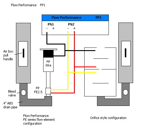
Here are the basic concept plans for an air box I am currently constructing. It will be attached to the wall and some 4" ABS plastic drain pipe will plumb the air into the bottom of an orifice plenum/settling chamber, or a Flow Performance flow element.
The grey box section slides left and right inside the red frame section to establish the air direction. The bleed valve regulates the test pressure. The weight of the grey box forms the seal on the bottom section of the red frame.
My box will hold 8 motors, and is 4' tall.
The column style motor box allows the use of flapper valves at each motor (Mine is 1/2/2/3 motors per valve). The valves are made from 1/16" #30 softness sheet rubber with 1/4" foam cell PVC backing. All frame and box pieces are melamine. The grey box section slides very esily on the red frame using melamine.
A nice concept mouse. I think the wall mount idea has a lot of merit.
Where are you getting the material for your flapper valves and do you have any pics of them for the board?
Tom V.
Where are you getting the material for your flapper valves and do you have any pics of them for the board?
Tom V.
Tom,
The sheet rubber is from McMaster, and the Foam core PVC can be bought from TAPP Plastics. The FCPVC is very light weight, ridgid and tends to stay flat or straight. The rubber is glued to the FCPVC with contact cement and pressed between two pieces of melamine while setting to make the rubber very flat (no lumps).
I will post some pics and drawings when I get a chance.
John
John,what exactlly is required to convert the mercdog bench to your box?
I don't know exactly, I am not that familiar with that design.
Here is a side view drawing of application.
Here is a side view drawing of application.
Well for those who have already done this what are the steps involved in converting any other orifice style bench over to your FP1 system?I read the thread with Chad but it turned into something else.Do I just tee into the manometers?
The FP1 simply hooks straight up to existing manometer connections at the bench. You still need to reverse the connections for flow reversal ie. Intake to Exhaust. the connections on the FP1 unit itself are easy to hook and unhook with the rubber connectors that ship with the unit.
Larry
Larry
Fkned,
I personally didn't get steady readings by teeing into the manometers. The FP jumped around. I just hooked it back up direct and solved the problem. I think the FP is so quick, it was reading the manometers jumping around. Needless to say, once I deleted the manometers, I never hooked them back up. FP all the way!
I personally didn't get steady readings by teeing into the manometers. The FP jumped around. I just hooked it back up direct and solved the problem. I think the FP is so quick, it was reading the manometers jumping around. Needless to say, once I deleted the manometers, I never hooked them back up. FP all the way!