
FlowBench for 150 to 210 cfm heads - FlowBench Materials
![]() by 200cfm » Tue Nov 28, 2006 12:36 am
by 200cfm » Tue Nov 28, 2006 12:36 am
Ok, I notice on the superflow design the first orifice is very small. Around .312" And I have learned that the cfm flow demand needs can be adjusted by adding or removing stoppers. It appears a .312 orifice would give some "fine tuning" control for the bench. Would this 4th potential orifice plate be beneficial for my head intake ranges?
- 200cfm
- Posts: 302
- Joined: Fri Nov 17, 2006 10:52 pm
- Location: Virginia
![]() by 200cfm » Tue Dec 12, 2006 10:11 pm
by 200cfm » Tue Dec 12, 2006 10:11 pm
No feedback on the .312 trimming orifice means I don't need one correct? Ok, have started gathering parts along with more research readings. Bought a 30-0-30 Dwyer slack tube manometer on ebay. Here is a photo. I plan to use this for the vertical manometer. Will this be sufficient?
Dwyer slack tube:
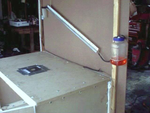
Another view of the incline.
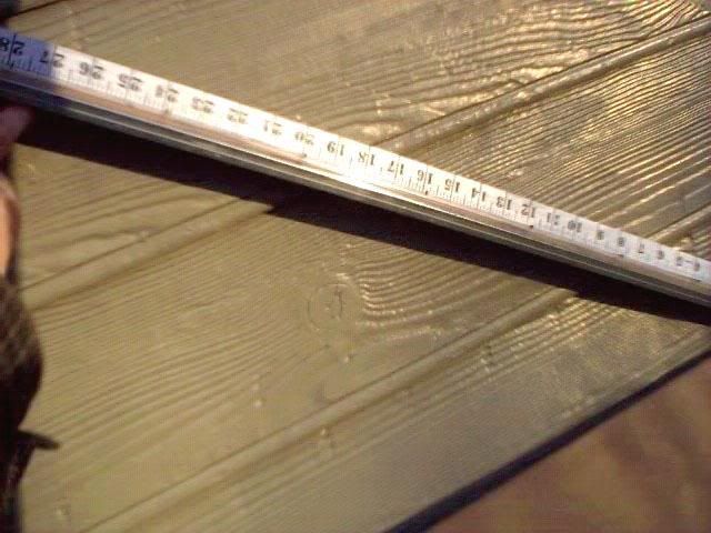
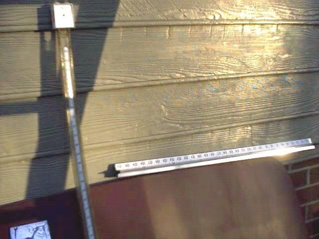
And next to it is my DIY vertical manometer. Scale is 0 to 31.5 but I plan to go 12" WC with 100% at the 28" mark. Tubing is plastic 1/4". Bottom portion is aluminum piece used on mirrors. It is nailed to a cut piece of 1 X .500 wood. Serves as a straight edge for the tubing. Tubing is secured by very tiny nails spaced about 4 inches apart for a snap in "pressure retension fit." Scales is my wifes cloth measuring tape sacrificed for the project. It is glued to the wood board using 3M adhesive glue. Tubing ends are tapped with some couplings I had from a minivac brake bleed kit. They fit in the 1/4 inch tube nice and tight. Ends are tapered down and will connect to a 1/8 or 1/16 inch windshield washer tubing. Haven't made the reservoirs yet, but the plates are on order from Bruce.
Am I on track so far?
Dwyer slack tube:
Another view of the incline.
And next to it is my DIY vertical manometer. Scale is 0 to 31.5 but I plan to go 12" WC with 100% at the 28" mark. Tubing is plastic 1/4". Bottom portion is aluminum piece used on mirrors. It is nailed to a cut piece of 1 X .500 wood. Serves as a straight edge for the tubing. Tubing is secured by very tiny nails spaced about 4 inches apart for a snap in "pressure retension fit." Scales is my wifes cloth measuring tape sacrificed for the project. It is glued to the wood board using 3M adhesive glue. Tubing ends are tapped with some couplings I had from a minivac brake bleed kit. They fit in the 1/4 inch tube nice and tight. Ends are tapered down and will connect to a 1/8 or 1/16 inch windshield washer tubing. Haven't made the reservoirs yet, but the plates are on order from Bruce.
Am I on track so far?
- 200cfm
- Posts: 302
- Joined: Fri Nov 17, 2006 10:52 pm
- Location: Virginia
![]() by DaveMcLain » Wed Dec 13, 2006 10:43 am
by DaveMcLain » Wed Dec 13, 2006 10:43 am
On the Superflow 110 they don't recommend running the bench with all of the holes in the orifice plate covered, that's why they give you 5 plugs for 6 holes. The smallest hole is much larger than .312, more like 5/8 inch, it's the 10cfm scale orifice.
Also, on the Superflow I think they use about 2 inches of water pressure drop on the inclined manometer across the orifice plate. The SF300 and SF600 use higher depressions across the orifice plate and a longer inclined manometer and what's interesting about those machines is how Superflow used the the same inclined manometer when the 600 came out with a greater number of motors than the SF300, they just changed to a different gauge fluid, blue instead of red to allow it to function with a higher depression across the orifice plate than the SF300.
Also, on the Superflow I think they use about 2 inches of water pressure drop on the inclined manometer across the orifice plate. The SF300 and SF600 use higher depressions across the orifice plate and a longer inclined manometer and what's interesting about those machines is how Superflow used the the same inclined manometer when the 600 came out with a greater number of motors than the SF300, they just changed to a different gauge fluid, blue instead of red to allow it to function with a higher depression across the orifice plate than the SF300.
- DaveMcLain
- Posts: 110
- Joined: Sat Jan 01, 2005 10:30 am
- Location: Cuba MO USA
![]() by 200cfm » Tue Dec 19, 2006 10:41 pm
by 200cfm » Tue Dec 19, 2006 10:41 pm
Went to Boaters World and picked up the marine deck plates for the front panel. Selected two 8" clear screwout Beckson deckplates. Chose the clear so I could see the inside of the chamber and confirm the orifice selected and keep an eye on the stoppers. Chose the 8 inch size because I wanted the extra elbo room to remove and install the orifice plate.
Thinking of hanging string down from the ceiling orifice flow chamber to monitor the dreaded turbulence that everyone says screws up the flow to the measuring orifice. Has this been done before?
Should wag violently if air is upset I would think.
Then went on to Home Depot to eyeball potential things. They have 1/8" by 20 ft vinyl tubing so picked up a pack to run the lines from the 1/4 dia manometers to the chambers, etc. And got some wood liguid nails, caulking sealer, etc.
In the washer dryer section there is a ceiling diffuser device that is adjustable for air ceiling venting. Looked like a potential air valve controller for the intake and exhaust chambers with some modifications. It has a good mounting feature already built in. Just needs a board with a hole and a few bolts. And it adjusts out by rotating on a 1/4 bolt threaded through the housing bushings. If the bolt was extended on out by a coupler it could become a long rod for a knob to be attached. Only weak point was when adjusted "close" there was still a slight leak between the diffuser and main housing. Could be sealed by an O ring insert perhaps or a silicone seal or housing modified for a more precision closure. Check it out and see if it offers what I think I see.
Also in the same section there is a dryer hose one way valve that looks idea for a motor to prevent back air flow when off. Didn't get it because haven't gotten the motors yet, but the size looks, well almost perfect. Anyone used one of those before?
Question on the wood for the bench. Which is the best from a construction, strength and weight comparison. 3/4 plywood, 3/4 particle board or 3/4 MPD. I have never had to cut or nail MPD and was surprised at the weight of one sheet. But I am not please with how particle board behaves sometime either with a saw. Leaning toward plain 3/4 plywood at the momemt.
Still looking into the motors. Leaning toward the Surplus Center model for $$$$ reasons. But readings say a two stage motor is better. What is the difference between a one stage and a two stage 110 motor? Goal is 200 cfm potential at test pressure of 28." Is 4 motors sufficient? Thanks and Merry Christmas to all.
- 200cfm
- Posts: 302
- Joined: Fri Nov 17, 2006 10:52 pm
- Location: Virginia
![]() by larrycavan » Thu Dec 21, 2006 2:36 pm
by larrycavan » Thu Dec 21, 2006 2:36 pm
I'd go with at least 6 of the Surplus Center single stage motors. You want some breathing room...no pun intended.
- larrycavan
- Site Admin
- Posts: 1183
- Joined: Fri Apr 01, 2005 4:40 pm
![]() by 200cfm » Thu Dec 21, 2006 11:49 pm
by 200cfm » Thu Dec 21, 2006 11:49 pm
Ok, thanks. Bought a 3/4 4X8 sheet of MPD today. Decided to go MPD because of density and strength over the other choices.
Bruce, I got the three orifice plates and calibration plate today in the mail. Very nicely done. Thanks. Hope to get the motors in the coming new year.
Bruce, I got the three orifice plates and calibration plate today in the mail. Very nicely done. Thanks. Hope to get the motors in the coming new year.
- 200cfm
- Posts: 302
- Joined: Fri Nov 17, 2006 10:52 pm
- Location: Virginia
![]() by 200cfm » Wed Dec 27, 2006 11:02 pm
by 200cfm » Wed Dec 27, 2006 11:02 pm
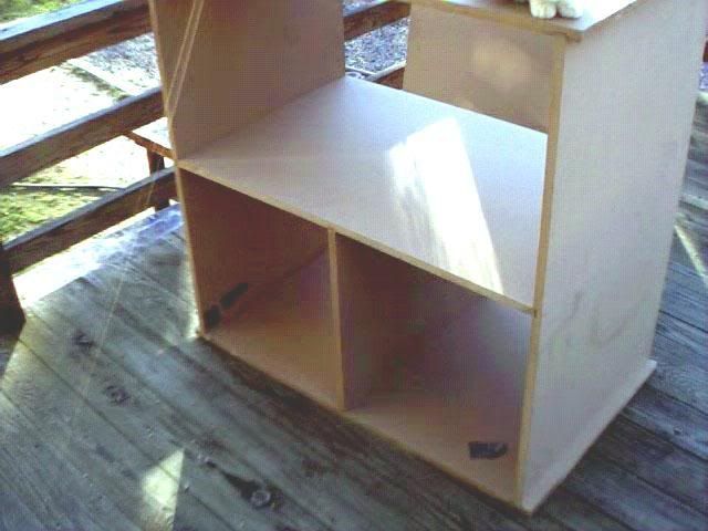
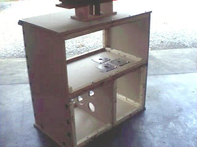
Have started the basic frame dry mock up and layout of where I think the plates will go. Have cut up three sheets of MPD board. Front and rear panels are not shown. And will add more frame support on the inside. Got one good used vacumn cleaner motor rated at 9 amps. Five motors to go. Upper chamber is rather large and should offer good air settlement before "seeing the orifice." Motor board has room for a max of 6 motors (I hope.)
How is the wiring cable passed through the lower cavity by other builders? What designs ares better for seal, etc? I am thinking of a female plug on the outside panel board.
How is the wiring cable passed through the lower cavity by other builders? What designs ares better for seal, etc? I am thinking of a female plug on the outside panel board.
- 200cfm
- Posts: 302
- Joined: Fri Nov 17, 2006 10:52 pm
- Location: Virginia
![]() by 200cfm » Mon Jan 08, 2007 10:49 pm
by 200cfm » Mon Jan 08, 2007 10:49 pm
Bruce, what is the flow direction on the plates? Does the flat side of orifice edge face the air flow or does the side that has an angle cut face the air flow? And how big should the hole beneath the plate be? This MPD board is 3/4" thick so is a 2.5" hole saw hole adequate? Largest orifice is 1.905"
Not pleased with this MPD. Should have gone plywood for board material.
Not pleased with this MPD. Should have gone plywood for board material.
- 200cfm
- Posts: 302
- Joined: Fri Nov 17, 2006 10:52 pm
- Location: Virginia
![]() by 200cfm » Tue Jan 16, 2007 9:45 pm
by 200cfm » Tue Jan 16, 2007 9:45 pm
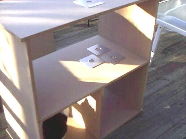
Have started the internal framing and bracing. And made a model mock up of the cylinder bore adapter. Cylinder is a 3.680 X 6 X .093 Ford engine sleeve. Have not designed the air valve controller yet.
Does the control valve go between the suction side of the motors and the orifice plate board? And if so, isn't that the same as having a parallel variable orifice hole? I am having a problem picturing where to put the control valve for test pressure depression control. I hope I am not missing a chamber or cavity in this design.
Here is a photo:
I have gathered 4 motors and have cut holes/slots for three.
The strongest one seems to be a Hoover motor that pulls only 7.5 amps but it has a large plastic propeller and scroll much like a turbo and is two stage. Others are single stage. It really blows some air as far as volume.
I have abandoned the dual intake and exhaust mode design. Current construction design is all intake suction. The research files indicate the exhaust port can be flowed the same direction as the intake port for a valid cfm measurement so it didn't seem practical to stress the bench with internal pressure and have extra holes and ports cut for dual direction flow etc. . Was this wise?
I started with a goal of 28 inch test depression with 12" incline. If the motors want pull that much can I still use the three orifice plates at a lower test pressure, say 15 or 10 wc and change the incline height to say 6 or 10" wc.?
- 200cfm
- Posts: 302
- Joined: Fri Nov 17, 2006 10:52 pm
- Location: Virginia
![]() by 200cfm » Wed Jan 24, 2007 11:09 pm
by 200cfm » Wed Jan 24, 2007 11:09 pm
Ok, I think I am making progress. Have installed 4 motors and got them running. Got the back board built and manometers hung and adjusted. Made some sensor pick up probes out of brass tubing. Finished the basic internal framing and hung the front door. Still need to add additional bracing. Rigged up a temporary reservoir. Made the first test firing and with two motors roaring I got 8.8" wc on test pressure and 21 inch mark on flow incline manometer. That converted to 8.51 inch wc @ about 66.3 cfm. Test was with A + D motor. Both manometers were rock steady and repeatable measurements. Didn't switch in B or C motors because not sure of chamber strength. Twas a Happy Day to see that red fluid rise!
- 200cfm
- Posts: 302
- Joined: Fri Nov 17, 2006 10:52 pm
- Location: Virginia
![]() by 200cfm » Thu Jan 25, 2007 10:42 pm
by 200cfm » Thu Jan 25, 2007 10:42 pm
Thanks Larry. I worked in the cold garage again today trying to further the project along. "Flowbench mania" kept me warm and inspired. Here are some photos and the new issues discovered.
First photo is the motor side. There are 4 motors tucked away in the middle board. Two eureka's, one electrolux, and one turbo like Hoover. On single motor runs the Hoover pulls the most test depression and incline flow. The electrolux is the smallest and the weakest.
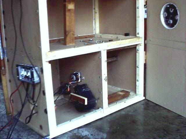
The current demand was the least on the Hoover so I selected that motor for the rehostat controller. Testings showed a control range from idle to full blast. I decided to stay away from the air valve design unless absolutely needed.
I added some 2X4 bracing support in the top chamber and suction chamber before testing all 4 motors together. But I didn't glue or nail them down because I wanted to confirm they did not disrupt the air settling capacity of the depression chamber. The are "wedged pressed" for now.
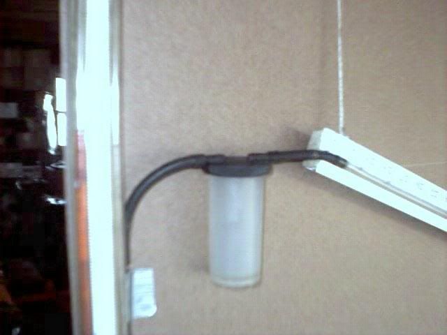
The top board needed some refinements so I added a reservoir overflow for the incline. I was seeing a potential to overflow if the wrong orifice was selected with all 4 motors on.
And I rearranged the sensing lines. The top of the incline manometer is secured only by an adjustable string in case I need to lower the current 12" wc max reference at 30."
The overflow is a simple brake bleeder container. It is air tight and offered attachment ports. Here is a photo.
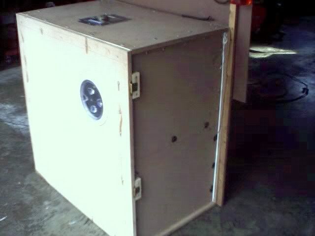
I added cabinet hinges to the front panel becausei t was a pain to align and start the screws. Now I can gain entry in a few minutes.
The port hole is 8" and gives excellent entry to the orifice plates. I bought two rubber stoppers but couldn't find one size for the largest orifice. So instead I used duct tape on that orifice when not needed. I discovered it was difficult to open the port hole door by hand so I rigged up a wooden bar with protruding "keys" to fit into the port door turn slots.
Here is a view of the swing door front and port hole.
I was having difficulty knowing exactly when the fluid was at zero reservoir height because of a design flaw. The cure was to extend the clear vinyl tube an inch below the zero reference point ( a negative one inch). This allowed an accurate zero inch start fluid flow mark. A string holds the reservoir which is a mayonaize jar (hard thick plastic). It offers about a 3.5 inch ID. I am trying not to nail or glue down to much until I debugg the bench.
Here is a better view of the top board. The incline is angled for 12" wc at 30"
Now for today's testing results.
With the largest orifice plate selected (1.950") and 4 motors running I was able to reach slightly more than 31" wc test depression. It might have gone a tad higher but I didn't want to exceed anything so I regulated the Hoover motor to keep it at 28" wc vertical manometer.
The first photo was taken with the dual Dwyer manometer level reaching my first 28" wc test depression. I was elated!
You can see the number but it was reading 14" wc and since it is a dual Dwyer it becomes my first 28" wc.
Now on this test I have Bruces calibration plate on the top bore entry hole secured down with duct tape. It is calibrated for 115 cfm @ 28" on a 1.266" diameter orifice.
So I read the incline and the level is reading 20 5/8 inches or 20.625". I looked this value up on the excel sheet and it converts over to about 83% flow. I believe this is 83% of the selected orifice which flows 178.6 cfm @ 28". So I calculated 148.2 cfm flow through the selected orifice.
Shouldn't the flow have calculated to 115 cfm at 12.38" instead of 20.625"????????
I fear now I have a serious leak somewhere unless I am testing something incorrectly. The other two orifice plates are 1.300" and 1.650"
This is as far as I could take things today. Bruce, Larry, Thomas, Anyone with insight on these results, please advise.
If I have an error please point it out.
I am so happy to have a test depression potential of 28" wc without bench collapse but depressed that I may have a serious bench seal leak somewhere. Comments, feeback, critique are welcome. Thanks.
[B]
First photo is the motor side. There are 4 motors tucked away in the middle board. Two eureka's, one electrolux, and one turbo like Hoover. On single motor runs the Hoover pulls the most test depression and incline flow. The electrolux is the smallest and the weakest.
The current demand was the least on the Hoover so I selected that motor for the rehostat controller. Testings showed a control range from idle to full blast. I decided to stay away from the air valve design unless absolutely needed.
I added some 2X4 bracing support in the top chamber and suction chamber before testing all 4 motors together. But I didn't glue or nail them down because I wanted to confirm they did not disrupt the air settling capacity of the depression chamber. The are "wedged pressed" for now.
The top board needed some refinements so I added a reservoir overflow for the incline. I was seeing a potential to overflow if the wrong orifice was selected with all 4 motors on.
And I rearranged the sensing lines. The top of the incline manometer is secured only by an adjustable string in case I need to lower the current 12" wc max reference at 30."
The overflow is a simple brake bleeder container. It is air tight and offered attachment ports. Here is a photo.
I added cabinet hinges to the front panel becausei t was a pain to align and start the screws. Now I can gain entry in a few minutes.
The port hole is 8" and gives excellent entry to the orifice plates. I bought two rubber stoppers but couldn't find one size for the largest orifice. So instead I used duct tape on that orifice when not needed. I discovered it was difficult to open the port hole door by hand so I rigged up a wooden bar with protruding "keys" to fit into the port door turn slots.
Here is a view of the swing door front and port hole.
I was having difficulty knowing exactly when the fluid was at zero reservoir height because of a design flaw. The cure was to extend the clear vinyl tube an inch below the zero reference point ( a negative one inch). This allowed an accurate zero inch start fluid flow mark. A string holds the reservoir which is a mayonaize jar (hard thick plastic). It offers about a 3.5 inch ID. I am trying not to nail or glue down to much until I debugg the bench.
Here is a better view of the top board. The incline is angled for 12" wc at 30"
Now for today's testing results.
With the largest orifice plate selected (1.950") and 4 motors running I was able to reach slightly more than 31" wc test depression. It might have gone a tad higher but I didn't want to exceed anything so I regulated the Hoover motor to keep it at 28" wc vertical manometer.
The first photo was taken with the dual Dwyer manometer level reaching my first 28" wc test depression. I was elated!
You can see the number but it was reading 14" wc and since it is a dual Dwyer it becomes my first 28" wc.
Now on this test I have Bruces calibration plate on the top bore entry hole secured down with duct tape. It is calibrated for 115 cfm @ 28" on a 1.266" diameter orifice.
So I read the incline and the level is reading 20 5/8 inches or 20.625". I looked this value up on the excel sheet and it converts over to about 83% flow. I believe this is 83% of the selected orifice which flows 178.6 cfm @ 28". So I calculated 148.2 cfm flow through the selected orifice.
Shouldn't the flow have calculated to 115 cfm at 12.38" instead of 20.625"????????
I fear now I have a serious leak somewhere unless I am testing something incorrectly. The other two orifice plates are 1.300" and 1.650"
This is as far as I could take things today. Bruce, Larry, Thomas, Anyone with insight on these results, please advise.
If I have an error please point it out.
I am so happy to have a test depression potential of 28" wc without bench collapse but depressed that I may have a serious bench seal leak somewhere. Comments, feeback, critique are welcome. Thanks.
[B]
- 200cfm
- Posts: 302
- Joined: Fri Nov 17, 2006 10:52 pm
- Location: Virginia
![]() by larrycavan » Fri Jan 26, 2007 2:23 am
by larrycavan » Fri Jan 26, 2007 2:23 am
- larrycavan
- Site Admin
- Posts: 1183
- Joined: Fri Apr 01, 2005 4:40 pm
![]() by 200cfm » Fri Jan 26, 2007 7:44 pm
by 200cfm » Fri Jan 26, 2007 7:44 pm
Ok, Larry, others, I completed the comparison manometer tests today as you suggested. The tracked very close. I moved the end of the flow manometer (string end) straight up to make a vertical manometer. And I adjusted the lines to sense pressure in parallel with the Dywer test manomter. Here are the results at various test pressures.
Test 1: Dwyer @ 12.6 wc flow manomter @ 12 1/2 wc
Test 2: Dwyer @ 20.5 wc flow manomoter @ 25 1/4 wc
Test 3: Dwyer @12.7 wc flow manomter @ 12 1/2 wc
Test 4: Dwyer @ 28 wc flow manomoter @ 27 6/8
I later repeated the above and saw no significant change so I think it is safe to say "close enough."
I did notice something peculiar with the Dwyer U tube slack design. Sometimes I have to do a slight scale adjustment (about 1/10). It's as if the fluid might not fully recover to the bottom and a drop or two are missing. And I notice something else. The negative column does not track 100% with the postive column. For example if one side rises to 12" wc the opposite side will be off anywhere from .1 to .2 " making 11.9 or 11.8 inch marks for a sum total test pressure of 23.9 or 23.8 if you count the missing tenths.
I thought perhaps the solution might be to double only one side (like the positive 12" wc side to make an even 24" wc. What could be causing this phenomena? Could it be the age of Dwyer slack tube. I bought it used (ebay) and the vinyl is yellowed more than I would prefer and dark spots are on the inside as if there is bacteria growing, etc. Could that affect the rising and falling of the test manometer?
The home made flow manometer drains back fine. Now and then I see one drop not returning to zero point but other than that fluid recovery seems fine.
I made the block flow tests as you suggested.
Calibration plate on top sealed off. Orifice plate selected is 1.950". Others are sealed off. The flow manomter still rises. Note: for these tests I have returned the flow manomter back to 12" incline rise. And I selected different motors to vary the depression.
Test 1: 8.8" wc Dwyer Flow manometer 3/4" mark
Test 2: 24.5" wc Dwyer Flow manometer 2.5" mark
Test 3: 28" wc Dwyer Flow manometer 3.5" mark
I repeated the above cycle tests several times and they were pretty much the same. I checked for leaks. Opened up the front and retorqued the three orifice plates bolts. Added some GE II Silicon. Repeated again the above and saw no significant changes.
The incline should have stayed at 0" correct if bench were perfectly sealed? Is my thinking correct?
Ideas, suggestions. Thanks.
- 200cfm
- Posts: 302
- Joined: Fri Nov 17, 2006 10:52 pm
- Location: Virginia
Return to Orifice Style bench discussion
Who is online
Users browsing this forum: No registered users and 8 guests