
FlowBench for 150 to 210 cfm heads - FlowBench Materials
![]() by SWR » Sun Feb 25, 2007 11:01 am
by SWR » Sun Feb 25, 2007 11:01 am
When intake testing,they pull from the chamber side. When exhaust testing,they pull from a pipe attached to the manifold flange. So the air moves in the right direction at all times. I use that technique myself,as my current bench design doesn't like to blow stuff backwards... 
- SWR
- Posts: 121
- Joined: Fri Dec 15, 2006 7:47 pm
- Location: Norway
![]() by Thomas Vaught » Mon Feb 26, 2007 9:22 pm
by Thomas Vaught » Mon Feb 26, 2007 9:22 pm
Biggest advantage I see is that the bench can be designed so that it is reinforced for only one direction of flowing.
You also can have consistant temperatures on all of your testing.
Ford uses a "Nozzle" type venturi system in a fixed mounting plate
much like this one:
web.cecs.pdx.edu/~gerry/epub/pdf/flowBenchManual.pdf
(You will have to paste the URL in the search bar). This shows the basic lay-out but is not the bench Ford has.
Tom V.
- Thomas Vaught
- Posts: 465
- Joined: Fri Feb 18, 2005 5:36 pm
- Location: Michigan
![]() by 200cfm » Fri Mar 16, 2007 10:10 am
by 200cfm » Fri Mar 16, 2007 10:10 am
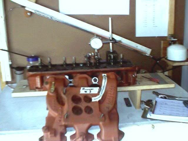
Guys, I am really enjoying my turbo 200 bench. Here are some numbers from a factory intake port number 3. Valve is 1.656."
lift cfm
.100 43.2
.200 73.9
.300 101.5
.400 119.6
.450 122.2
.490 129.6
No heavy breathing compared to other new stuff on the market and my cam is limited to .400 max but it is just nice to know where the base line is. With spring here I hope to get into porting 101 class soon.
lift cfm
.100 43.2
.200 73.9
.300 101.5
.400 119.6
.450 122.2
.490 129.6
No heavy breathing compared to other new stuff on the market and my cam is limited to .400 max but it is just nice to know where the base line is. With spring here I hope to get into porting 101 class soon.
- 200cfm
- Posts: 302
- Joined: Fri Nov 17, 2006 10:52 pm
- Location: Virginia
![]() by 200cfm » Mon Apr 16, 2007 10:29 pm
by 200cfm » Mon Apr 16, 2007 10:29 pm
Still enjoying the bench. So much to learn and evaluate. I find it difficult to see up inside the head intake port without holding a light in one hand. . Today I removed the port hole in the bench and held an extension lamp up under the cylinder bore of the head adapter. It offered a good viewing around the bowl and seat area (assuming you have modest lift) on the valve. So I am planning on installing an internal light in the chamber. Anyone doing something similiar to see the port and bowl when probing around? If you had a clear plastic bore cylinder would the light back feed up into the bowl?
- 200cfm
- Posts: 302
- Joined: Fri Nov 17, 2006 10:52 pm
- Location: Virginia
![]() by Thomas Vaught » Tue Apr 17, 2007 7:19 pm
by Thomas Vaught » Tue Apr 17, 2007 7:19 pm
As many know, most of the benches on the forum have gone to a baffle
between the cylinder discharge and the orifice plate(s) holes.
I went to a mirror shop and got a 6"x6" mirror and mounted it to the
bottom of the plexiglas baffle (at the correct 45 degree angle) so that I could see up into the cylinder during flow testing through a clear port hole cover. Using a flashlight shining on the mirror allowed me to see the valves.
If I change it, I will get a couple of the battery powered LEDs and mount
them to shine into the bore for a less obstructed view. I thought I was
going to use a pipe tabaco smoke generator to make smoke but haven't got that far yet.
Tom V.
- Thomas Vaught
- Posts: 465
- Joined: Fri Feb 18, 2005 5:36 pm
- Location: Michigan
![]() by rusty105 » Tue Apr 17, 2007 8:08 pm
by rusty105 » Tue Apr 17, 2007 8:08 pm
Has anyone thought about using a cheap web cam as a remote mounted 'eye' into the chamber, along with some LEDs for light, I think you would be able to see up into the chamber no problem. Of course I haven't even started building my bench, but I was thinking about trying this once I had it up and running. I don't think it would be too much of a drain on a semi modern PC or Laptop.
Just an idea
Just an idea
Rusty
Race Car Design and Fabrication Forums
Race Car Design and Fabrication Forums
- rusty105
- Posts: 37
- Joined: Fri Jan 05, 2007 9:12 pm
- Location: NY
![]() by 200cfm » Tue Apr 17, 2007 10:39 pm
by 200cfm » Tue Apr 17, 2007 10:39 pm
That's a good idea. I built my first prototype pitot J bend probe today. Actually built two. First one worked but I didn't like the size and noticed it caused what I thought was excessive test depression change. So the second prototype was thinner tubing and smaller J turn. Got it down to .059" for the J portion and the two tubings together came in at .180. Used a third manometer vertical U dwyer for detection. Did my first velocity probing around and I must say this is a challenge both in trying to understand and interpret what is going on. I was surprised at the height of the inch rise. Good thing I had this spare long U slack tuber.
But I still have some test depression swing when inserting the probe.
I have a few questions.
1. What should be the valve lift when looking for air speed? I set up for .400"
2. What test depression is air speed to be validated at for a port. I set up for 28" wc test depression. But that much puts a strain on my motors for the time period of probing around. And it requires the back and forth tweaking to keep the test depression holding at 28". Can this be done at a lower test depression and recalculated up for a 28" wc reference?
3. What is the best gauging method to reference the distances and locations in the port. I put little "ink markings" on the pitot probe to give some depth reference. And I sketched out a port layout on graph paper from the mold on the intake I made. But there must be a better way.
4. Is this the correct forumula? fps = square root of pitot pressure reading times 66.2
5. I took a lot of readings and from the best I can interpret I am getting the fastest air right at beginning turn of what in the port is the "pushrod turn curve." top, middle, and bottom of this left wall turn (port number 3) is reading 22/21/20.3 max. So I calculated that to be 313/303/298 fps. This was about the fast part of the port I could find. I get about 18" wc on the SSR which became 280 fps if I am doing this correctly. And the roof of the SSR gave about the same reading. I was expecting the SSR to be faster.
One final note: I made my first "string flow" tester and this is what I noticed. String stays nice and straight along the floor from entrance to beyond the SSR. And I could float it a good 1/4 inch plus off the floor. The strings stays straight also on the right wall for a good distance. But if I walk it along the entrance on the left wall it is straight until it enters into the Pushrod curve and from that point on it starts spinning like a propeller. The deeper the string goes the more it swirls and it appears to be a CCW rotation. It is really spinning all the way back to the bowl and valve stem. Do these areas behave like that on the good stuff? If I had a close up camera I could explain this better by a photo. It is like a vortex beyond that curve even though the CSA of the port is expanding and evolving into the bowl. Didn't expect a whirlwind.
I can post a photo of the port mold if that will help.
So much to learn. So little time!
- 200cfm
- Posts: 302
- Joined: Fri Nov 17, 2006 10:52 pm
- Location: Virginia
![]() by rusty105 » Wed Apr 18, 2007 7:58 am
by rusty105 » Wed Apr 18, 2007 7:58 am
A comment about your string theory...
It sounds like the flow is laminar just before the pushrod pinch or curve, as you get passed the pushrod pinch area that wall diverges, causing the flow to go turbulent. From the engineering classes I had years ago, and reading on other forums, air converges better then it diverges. Try filling that area beyond the pushrod with some modeling clay, smooth it out, then re-flow, and see what happens. The solution 'MAY' be to grind out that pushrod 'pinch' or curve. If you want, check out Speed Talk Forums. I have spent days reading about the pit falls of porting, and what should and should not be done.
BIG NOTE: I have no experience with these heads, and have no idea what they look like, but if they are like a small block Ford head. The pushrod pinch area is rough. A lot of people grind this hump out to the point of breaking through to the pushrod area, then sleeve the pushrod area, and smooth it out with epoxy.
Rusty
Race Car Design and Fabrication Forums
Race Car Design and Fabrication Forums
- rusty105
- Posts: 37
- Joined: Fri Jan 05, 2007 9:12 pm
- Location: NY
![]() by 200cfm » Wed Apr 18, 2007 10:32 am
by 200cfm » Wed Apr 18, 2007 10:32 am
Thanks, here are some photos.
Port floor
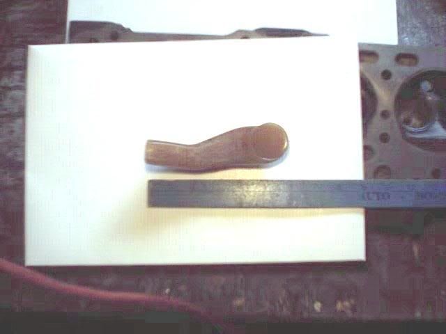
Port sidewall angles as viewed from roof
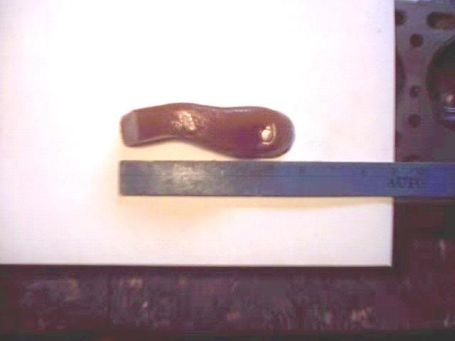
Roof and floor curves.
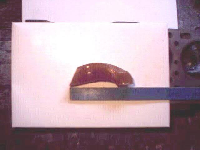
The sharpest turn or bend is the pushrod turn area. Getting a CSA of 1.395 sq. inch area here. Port is flowing 137.9 cfm at .400 lift. Valve is 1.656" 45 degree seat. Centerline length is 5.250."
Correction, the pitot J bend is .590"
Port floor
Port sidewall angles as viewed from roof
Roof and floor curves.
The sharpest turn or bend is the pushrod turn area. Getting a CSA of 1.395 sq. inch area here. Port is flowing 137.9 cfm at .400 lift. Valve is 1.656" 45 degree seat. Centerline length is 5.250."
Correction, the pitot J bend is .590"
- 200cfm
- Posts: 302
- Joined: Fri Nov 17, 2006 10:52 pm
- Location: Virginia
![]() by 200cfm » Wed Apr 18, 2007 10:05 pm
by 200cfm » Wed Apr 18, 2007 10:05 pm
These are from a 289 Studebaker V-8. The molds were made from RTV Urethane Rubber #74-30. Two part kit. Part A and part B. Sets up in 30 minutes and cures in 8 hours or less. Enough in the kit to do 3 , maybe 4 ports. Ordered it from US Composites West Palm Beach, Floridia Ordered by phone 561-588-1001. You will need the mold release Poly Ease 2300 spray can. Good stuff and they shipped promptly.
Had a good day at the office, ehh bench I mean. Answered a few of my own questions. Yes, you can get the fps at a lower pressure test. And once you have the data it can be converted back up to the 28" wc standard.
So I took some readings at 10" wc test depression. Took only two motors to pull that much. Noise is reduced and can run the bench much longer while probing. Then used the conversion formula to raise the values to 28" wc. To double check things I tested at a genuine 28". Almost dead on.
Now if I could only interpret the meaning of these air speeds as it relates to what helps and doesn't help.
- 200cfm
- Posts: 302
- Joined: Fri Nov 17, 2006 10:52 pm
- Location: Virginia
Return to Orifice Style bench discussion
Who is online
Users browsing this forum: No registered users and 3 guests