Page 1 of 1

Posted:
Thu Mar 04, 2004 6:14 pmby rbracer
Looking For any ideas for a tool to check valve lift on a side valve industrial engines wile flow testing
Posted:
Sat Mar 06, 2004 9:37 pmby willeng
rbracer:
You could get a micrometer mechanism & connect this to a small vertical slide with a right angle bracket on the bottom, maybe with a small slot in the end to fit the valve stem groove.
You could bolt this to the engine somehow for stability & position the right angled arm on the valve stem & turn the micrometer mechanism to adjust valve lifts.
If you need a quick drawing send us an E-mail
Posted:
Sat Mar 06, 2004 10:39 pmby 98-1074649673
Here is how I do it on my flathead engines.
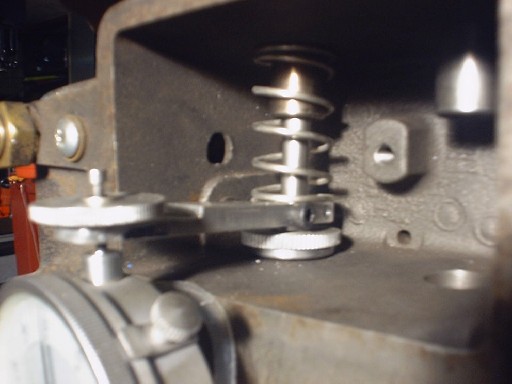
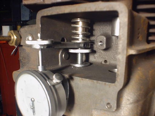
Should be self explanitory on how it works. Probably a tight fit on a Briggs block, works well on the cast iron Kohlers I work with. I have to come up with a similar setup to work on the Briggs 12hp alum block flatheads for engine development work I am getting into in the near future for the USLMRA racing tractor series.
Posted:
Tue Mar 09, 2004 5:20 pmby rbracer
Thanks for th idears will give them a try
Posted:
Fri Mar 12, 2004 2:25 pmby Shawn L
Hey all,
What is a good model and or p/n for an accurate yet inexpensive dial gauge similar to the above one?
Posted:
Fri Mar 12, 2004 3:14 pmby 98-1074649673
The one in the pic is from Harbor Freight on sale for $6.99. I had to cut the back lug off for my application. Simple, cheap and accurate enough for my application. I didn't care to destroy an expensive dial indicator for my setup. Hope that helps . . .