[phpBB Debug] PHP Warning: in file [ROOT]/includes/bbcode.php on line 483: preg_replace(): The /e modifier is no longer supported, use preg_replace_callback instead
[phpBB Debug] PHP Warning: in file [ROOT]/includes/bbcode.php on line 483: preg_replace(): The /e modifier is no longer supported, use preg_replace_callback instead
[phpBB Debug] PHP Warning: in file [ROOT]/includes/bbcode.php on line 483: preg_replace(): The /e modifier is no longer supported, use preg_replace_callback instead
[phpBB Debug] PHP Warning: in file [ROOT]/includes/bbcode.php on line 483: preg_replace(): The /e modifier is no longer supported, use preg_replace_callback instead
[phpBB Debug] PHP Warning: in file [ROOT]/includes/bbcode.php on line 483: preg_replace(): The /e modifier is no longer supported, use preg_replace_callback instead
[phpBB Debug] PHP Warning: in file [ROOT]/includes/bbcode.php on line 483: preg_replace(): The /e modifier is no longer supported, use preg_replace_callback instead
[phpBB Debug] PHP Warning: in file [ROOT]/includes/bbcode.php on line 483: preg_replace(): The /e modifier is no longer supported, use preg_replace_callback instead
[phpBB Debug] PHP Warning: in file [ROOT]/includes/bbcode.php on line 483: preg_replace(): The /e modifier is no longer supported, use preg_replace_callback instead
[phpBB Debug] PHP Warning: in file [ROOT]/includes/bbcode.php on line 483: preg_replace(): The /e modifier is no longer supported, use preg_replace_callback instead
[phpBB Debug] PHP Warning: in file [ROOT]/includes/bbcode.php on line 483: preg_replace(): The /e modifier is no longer supported, use preg_replace_callback instead
[phpBB Debug] PHP Warning: in file [ROOT]/includes/bbcode.php on line 483: preg_replace(): The /e modifier is no longer supported, use preg_replace_callback instead
[phpBB Debug] PHP Warning: in file [ROOT]/includes/bbcode.php on line 483: preg_replace(): The /e modifier is no longer supported, use preg_replace_callback instead
[phpBB Debug] PHP Warning: in file [ROOT]/includes/bbcode.php on line 483: preg_replace(): The /e modifier is no longer supported, use preg_replace_callback instead
[phpBB Debug] PHP Warning: in file [ROOT]/includes/bbcode.php on line 483: preg_replace(): The /e modifier is no longer supported, use preg_replace_callback instead
[phpBB Debug] PHP Warning: in file [ROOT]/includes/bbcode.php on line 483: preg_replace(): The /e modifier is no longer supported, use preg_replace_callback instead
[phpBB Debug] PHP Warning: in file [ROOT]/includes/bbcode.php on line 483: preg_replace(): The /e modifier is no longer supported, use preg_replace_callback instead
[phpBB Debug] PHP Warning: in file [ROOT]/includes/bbcode.php on line 483: preg_replace(): The /e modifier is no longer supported, use preg_replace_callback instead
[phpBB Debug] PHP Warning: in file [ROOT]/includes/bbcode.php on line 483: preg_replace(): The /e modifier is no longer supported, use preg_replace_callback instead
[phpBB Debug] PHP Warning: in file [ROOT]/includes/bbcode.php on line 483: preg_replace(): The /e modifier is no longer supported, use preg_replace_callback instead
[phpBB Debug] PHP Warning: in file [ROOT]/includes/bbcode.php on line 483: preg_replace(): The /e modifier is no longer supported, use preg_replace_callback instead
[phpBB Debug] PHP Warning: in file [ROOT]/includes/bbcode.php on line 483: preg_replace(): The /e modifier is no longer supported, use preg_replace_callback instead
[phpBB Debug] PHP Warning: in file [ROOT]/includes/bbcode.php on line 483: preg_replace(): The /e modifier is no longer supported, use preg_replace_callback instead
[phpBB Debug] PHP Warning: in file [ROOT]/includes/bbcode.php on line 483: preg_replace(): The /e modifier is no longer supported, use preg_replace_callback instead
[phpBB Debug] PHP Warning: in file [ROOT]/includes/bbcode.php on line 483: preg_replace(): The /e modifier is no longer supported, use preg_replace_callback instead
[phpBB Debug] PHP Warning: in file [ROOT]/includes/bbcode.php on line 483: preg_replace(): The /e modifier is no longer supported, use preg_replace_callback instead
[phpBB Debug] PHP Warning: in file [ROOT]/includes/bbcode.php on line 483: preg_replace(): The /e modifier is no longer supported, use preg_replace_callback instead
[phpBB Debug] PHP Warning: in file [ROOT]/includes/bbcode.php on line 112: preg_replace(): The /e modifier is no longer supported, use preg_replace_callback instead
[phpBB Debug] PHP Warning: in file [ROOT]/includes/bbcode.php on line 112: preg_replace(): The /e modifier is no longer supported, use preg_replace_callback instead
[phpBB Debug] PHP Warning: in file [ROOT]/includes/bbcode.php on line 112: preg_replace(): The /e modifier is no longer supported, use preg_replace_callback instead
[phpBB Debug] PHP Warning: in file [ROOT]/includes/functions.php on line 4752: Cannot modify header information - headers already sent by (output started at [ROOT]/includes/functions.php:3887)
[phpBB Debug] PHP Warning: in file [ROOT]/includes/functions.php on line 4754: Cannot modify header information - headers already sent by (output started at [ROOT]/includes/functions.php:3887)
[phpBB Debug] PHP Warning: in file [ROOT]/includes/functions.php on line 4755: Cannot modify header information - headers already sent by (output started at [ROOT]/includes/functions.php:3887)
[phpBB Debug] PHP Warning: in file [ROOT]/includes/functions.php on line 4756: Cannot modify header information - headers already sent by (output started at [ROOT]/includes/functions.php:3887)
Tractorsport Flowbench Forum Archive • View topic - Big blower single direction orifice bench

Big blower single direction orifice bench

A place to post links to your flowbench projects to share with everyone on the board.  You can share a description and pics also here please limit the size of your picture files to low res pics, Thanks

Postby Tony » Sat May 05, 2007 2:13 am

This is my third attempt at building a flow bench, and when it was built several years ago, it was at the time, a fairly radical departure from what everyone else was using.

At the moment it is incomplete, being half way thorough yet another upgrade, and being moved to a different location. Although there is enough of it shown here to get a general impression of the design philosophy and construction.

Image

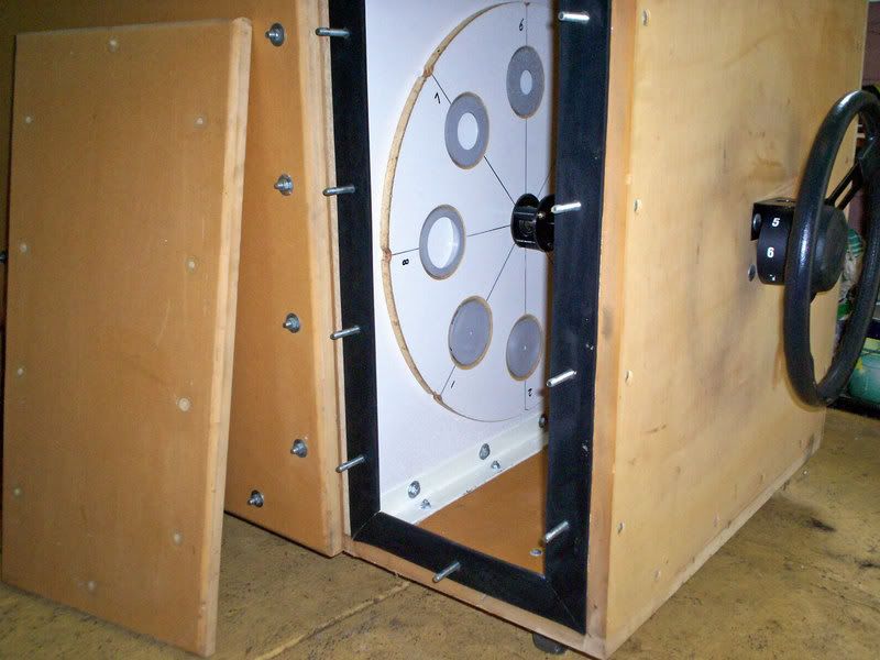
As you can see there are two test holes. The one on the left blows, and the one on the right sucks. Flow direction through the bench is always in the same direction, and that greatly simplifies construction, and avoids a lot of potential problems.

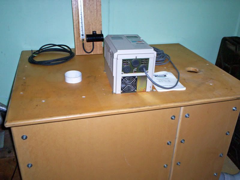
On top of the bench is a 10Hp rated variable frequency drive that can run motors up to 15Hp, provided care is taken to avoid excessive peak loading during acceleration. Also there is the test pressure manometer. The sloping manometer is of similar construction, but is being completely rebuilt at the moment. Later I may go electronic, but not during this upgrade.

The suction test hole leads straight down into a settling chamber, in which is located a two foot diameter orifice turret with eight removable and interchangeable orifice plates.

Image

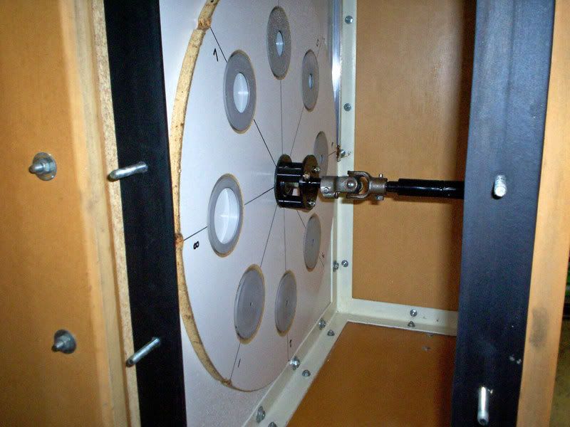
These orifice plates are made from PVC out of standard 90mm storm water pipe, end blanking plugs. These 90mm plugs are a tight press fit into a 3.5 inch hole cut with a holesaw. (3.5" = 88.9mm). The orifice plate holes were bored on a lathe, and there are eight different diameter orifices all with 2:1 flow ranges going from 800 CFM down to 6.25 CFM.

The turret has a self aligning central ball bearing, and rotates on a fixed bolt. There is also a spring to load the turret against the bulkhead, but air pressure also assists in sealing. On the outer circumference of the turret is a spring loaded roller to index the orifice over the hole through into the blower compartment.

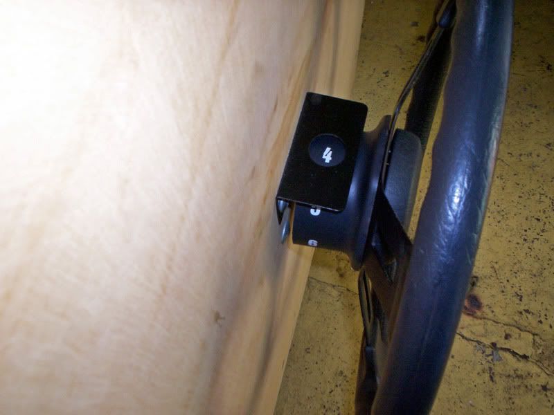
A steering wheel ! on the side of the bench also has a display to show which orifice is in position.

Image

Image

Construction of the bench uses two frames of welded steel angle, with a bulkhead sandwiched in between. The outer panels are all one inch MDF bolted and glued to the steel frame. It has never leaked right from the day it was first assembled.

The front access covers use thick sponge neoprene gaskets, and with a rattle gun, the covers can be be removed in less than a minute, and replaced in less than five minutes. This can be done countless times without any chance of slight leaks developing.

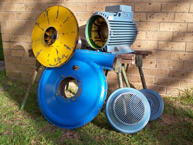
The left hand compartment houses the blower.

Image

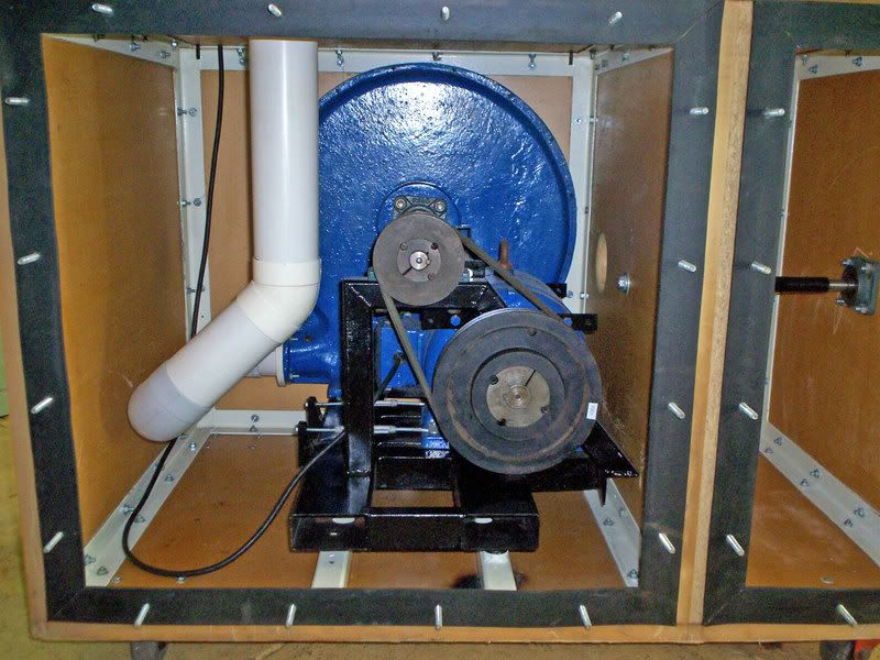
A 10Hp three phase motor drives the blower through a 2:1 speed increase with dual drive belts. It slips rather badly, at least four drive belts should really be used. The problems I have had with this pulley drive system are the main reason for upgrading the blower. My next blower will be the Aerotech, direct driven from a flange mount 15 Hp motor. No pulleys yipeee !!!


The black metal frame of the blower and drive motor, are mounted on very soft springs to reduce noise and vibration transmission through to the outside. Usually the blow test hole is vented outside down a large storm water drain, and the whole bench is as quiet as a small window airconditioner, even when run flat out. That has to be so, because I have some problem neighbors only feet away. That is another fairly powerful reason to relocate the whole flow bench.

Image
Also known as the infamous "Warpspeed" on some other Forums.
Tony
 
Posts: 824
Joined: Sat Dec 03, 2005 12:34 pm
Location: Melbourne, Australia

Postby Thomas Vaught » Sat May 05, 2007 11:00 am

Very Nice Bench Tony, Thanks for the pics.

I have you looked into a cog belt system vs the multiple belt system? Just wondering.

Direct drive would be easier in the belt scheme but you are also using an additional 5 hp vs what you have today, right.

Can you provide some of the Basic dimensions on the bench to the forum too?

Height, width, and length of the box, pipe dimensions, orifice hole dimensions, diameter of the turnstyle, blower diameter, wiring schematic, so that people really appreciate the bench.

It looks so simple but obviously a LOT of thought went into the project.

Thanks

Tom V.
Thomas Vaught
 
Posts: 465
Joined: Fri Feb 18, 2005 5:36 pm
Location: Michigan

Postby bruce » Sat May 05, 2007 12:30 pm

Wow pics of Tony's bench, was beginning to wonder if they had camera technology in the "Outback" :D

For those that don't know we've been trying to get pics from Tony for the past couple of years of his flowbench, even offered to buy one of those disposable cameras and send it to him.

NICE BENCH! Makes me wanna build an orifice bench!

Hummm . . .
"There is no more formidable adversary than one who perceives he has nothing to lose." - Gen. George S. Patton
bruce
Site Admin
 
Posts: 1638
Joined: Sun May 09, 2004 12:17 pm

Postby racehead » Sat May 05, 2007 2:47 pm

Congratulations, Tony for a nice flowbench. It is simple to make one compared with other ones, very well constructed and also very strong.
I am thinking of making one but with vacuum motors for now
than in the future change to a centrifugal blower.
Something that those V belts need is a spring loaded wheel to put pressure on the flat side of the V belt, with a pivot in in the frame.
racehead
 
Posts: 14
Joined: Tue Jan 23, 2007 5:38 pm
Location: Portugal

Postby Tony » Sat May 05, 2007 7:42 pm

Tom V, I will take some measurements and post them later.

When I first built this bench I did not have the VFD, so the blower was initially run flat out at around 5,600 Rpm. I had originally planned to use a couple of throttle bodies to throttle/bypass the air to control airflow.

The blower air output was more than sufficient, but the belts just smoked for several seconds whenever full power was applied. The lights in the whole house dimmed, so I figured that the blower drive system needed some further development, (chuckle).

A toothed belt would certainly have fixed the slip problem, in fact I had seriously considered using an overhead cam drive belt complete with its original 2:1 pulleys, but that would have made the mechanical start up overload even more violent. A VFD was the obvious single solution to all these various problems, and it has all worked out very well indeed.

It was a fairly easy decision to select a 15 Hp two pole (2,850 rpm at 50Hz) drive motor for my next upgrade, although it does look rather large now that I have it. This motor will never see the full 15 Hp load, but it is no more difficult to fit an oversized motor to it now, than regret not having done so later on.

It is also a lot easier to just run the motor up to 100Hz (or more) instead of up to only 50Hz and then require a truly horrid and expensive 2:1 speed step up ratio. Direct drive will also be far more compact, more silent, and a lot more efficient.

I just need to buy a big chunk of aluminium plate to turn up a complete new motor front plate onto which I can then directly bolt the blower casing. A simple adaptor is not really practical, I need a whole custom motor end plate. I will then turn this pile of bits back into a working blower one day, but it is not a top priority right now, too many other projects on the go.

Image
Also known as the infamous "Warpspeed" on some other Forums.
Tony
 
Posts: 824
Joined: Sat Dec 03, 2005 12:34 pm
Location: Melbourne, Australia

Postby blownalcohol » Sat May 05, 2007 10:30 pm

Hi Tony,

Very nice bench.....you have definately done your homework.

I have a question when you get a minute. I don't mean to throw this thread off track, but feel this has some relevence to what this topic is addressing.

I built my bench initially with vacuum motors.....you might remember responding to some of my questions. I have since purchased a sonic air centrifugal blower, a 15HP 3 ph motor, and a vfd for this application. I am currently trying to decide on pulley layouts and would like your input.

I am trying to decide how fast I can safely turn my 15hp motor. It's rated at 3490 rpm, and I would prefer to not have to use anymore overdrive in my pulleys than necessary. The blower is designed to turn 20,000 rpm and sonic air sells the pulleys to do so, but if I could use less pulley overdrive and just turn the motor faster I think I would prefer to do so.

Do you have any input on how much one can "push" the manufacturer's rpm??? I think my vfd is capable of 400hz....pretty sure I don't want to go that far!!!

Thanks for any input you have, and again nice bench.

Jeff
Jeff Fagala
jdfperformance.com
blownalcohol
 
Posts: 21
Joined: Mon Feb 05, 2007 4:35 pm
Location: Plano, Texas

Postby Tony » Sat May 05, 2007 10:38 pm

O/k now for some dimensions.

Every country in the world except America now uses the metric system, and this bench was built to metric dimensions. Fortunately a standard six foot by four foot sheet of MDF will be slightly oversized, to what has now shrunk slightly to become 1.8m x 1.2m

The basic very rough overall dimensions were made so that the MDF outer panels could all be cut from half or quarter of a standard 6 x 4ft or 1.8 x 1.2m sheet with minimum wastage. This enables a standard counter top height of three feet to be used, which is pretty much a world wide standard for kitchens, and household appliances. It is a good working height when either standing, or seated on a bar stool. So the outside dimensions are all made fractionally smaller than four feet wide, three feet high, and three feet deep.

Two welded steel angle frames of inch and a half by one eighth inch angle were then fabricated. The basic dimensions are 350mm wide x 750 deep x 750mm high for the settling chamber, and 780mm wide x 750mm deep x 750 high for the blower enclosure.

After welding the whole thing, it will almost certainly become distorted, but if the original lengths were cut very precisely, it should pull back into shape. Diagonals can be forced apart with a homemade screw bottle jack, made from thick wall tube and some really large all thread. Diagonals can be pulled together with a heavy turnbuckle and some chain. If the welds are ground, you should end up with a pair of nice square very close fitting frames. Don't expect that bolting up the frame will close any gaps if the whole thing is badly twisted. The steel frames must be built very accurately.

I am mainly interested in smaller engines, so my test holes and basic flow areas were all based around 90mm PVC rainwater pipe (roughly 3.5 inches).

But if large capacity V8 engines are your thing, test holes of four or even five inches may be required. All the airflow paths will need to be scaled up in proportion. It is not the slightest bit of use having a five inch test hole, if your blower only has a two inch intake and outlet size. Air flows right through the whole bench, so try to keep all the flow dimensions an appropriate size for the job. The largest sized flow measurement orifice should be by far the most restrictive flow point in the whole bench.

All my pipework, the test holes, and the orifice plates are all made from 90mm PVC fittings which are a lovely tight press fit into a 3.5 inch hole.

My turret is 620mm in diameter. It needs to be large enough to fit the required number of orifices, but not so large that the orifices end up too close to the bench walls. I located my eight 90mm orifice plates on a 400mm diameter pitch circle. Air should be able to enter the orifice radially from every direction, and it should be mounted flush into the face of the turret.

The "blow" discharge pipe will probably need a static pitot pressure measurement probe, and a flow straightener, and try to keep the discharge pipe below the test hole as long and as straight as possible.

One of the less obvious design features of this bench is that both compartments always operate under considerable negative air pressure. This pulls the panels down tight onto the steel frame, reducing any tendency towards air leakage. Static air pressure also forces the turret tightly against the bulkhead. Air pressure actually assists in sealing the whole bench, which is definitely a very worthwhile thing to have. With the blower going, the turret is almost impossible to turn, air pressure can be a very powerful force.

The panels have been coated inside and out with clear estapol. This is the very smooth clear coating usually applied to bare wooden floors. It creates a very hard tough leak free surface.
Also known as the infamous "Warpspeed" on some other Forums.
Tony
 
Posts: 824
Joined: Sat Dec 03, 2005 12:34 pm
Location: Melbourne, Australia

Postby Tony » Sat May 05, 2007 11:22 pm

Also known as the infamous "Warpspeed" on some other Forums.
Tony
 
Posts: 824
Joined: Sat Dec 03, 2005 12:34 pm
Location: Melbourne, Australia

Postby Thomas Vaught » Sun May 06, 2007 3:19 pm

Jeff,

On your Sonic blower, does it have any kind of an internal step-up transmission like a Vortech, Vortron, or Pro Charger blower does?

Typical step-up on the older Vortech Blowers was 3.45 or 3.62 so 5000 motor rpm was about 17,250 or 18,100 blower rpm for that motor rpm.

Procharger has larger step-up rations of 4+ or 5+ to 1.

Tom V.

ps Thanks for the dimensions Tony. Is your new motor a three phase unit?
Thomas Vaught
 
Posts: 465
Joined: Fri Feb 18, 2005 5:36 pm
Location: Michigan

Postby Tony » Sun May 06, 2007 7:40 pm

Also known as the infamous "Warpspeed" on some other Forums.
Tony
 
Posts: 824
Joined: Sat Dec 03, 2005 12:34 pm
Location: Melbourne, Australia

Postby blownalcohol » Mon May 07, 2007 12:09 am

Jeff Fagala
jdfperformance.com
blownalcohol
 
Posts: 21
Joined: Mon Feb 05, 2007 4:35 pm
Location: Plano, Texas

Postby Tony » Mon May 07, 2007 8:39 pm

It amazes me that ordinary car alternator bearings run at typically three to four times crank speed. And they can run for twenty years or more on the original grease !

Jeff, why not just copy the Sonic design ? They have obviously done some testing, and it is proven to work. If it works for them, it should work for you. Vortron do something almost identical, so the concept is pretty well proven.
Also known as the infamous "Warpspeed" on some other Forums.
Tony
 
Posts: 824
Joined: Sat Dec 03, 2005 12:34 pm
Location: Melbourne, Australia

Postby gofaster » Sun Jan 13, 2008 2:36 am

I think the 15 hp 3 ph motor rpm limit is more relative to the spinning mass than the bearings. I've seen these motors run away after being overspeeded by their load. (AC cranes vs. gravity!) They literally blow apart. Very ugly!
Jim
gofaster
 
Posts: 237
Joined: Fri Jul 01, 2005 6:39 pm
Location: Indiana

Postby gte » Mon Mar 10, 2008 11:53 am

Where is that motor from?


Also, can you post specifics on the measuring equipment?
gte
 
Posts: 21
Joined: Sat Mar 08, 2008 12:15 am

Postby Tony » Mon Mar 10, 2008 4:07 pm

The motor is just a standard three phase two pole induction motor, the type commonly used throughout industry.

All I am using is a test pressure manometer that uses water with a one metre long scale, (39") and a sloping manometer that also uses water with a similar length scale marked off in percentage flow.
Also known as the infamous "Warpspeed" on some other Forums.
Tony
 
Posts: 824
Joined: Sat Dec 03, 2005 12:34 pm
Location: Melbourne, Australia

Next

Return to Readers Flowbench projects

Who is online

Users browsing this forum: No registered users and 2 guests

cron