Page 2 of 2

Posted:
Sun Mar 12, 2006 3:31 pmby SuperRunner
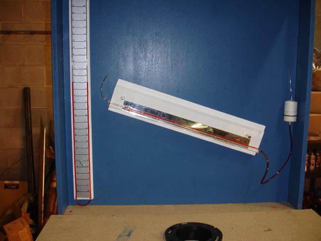
I fired it up last night with a 2 1/2 orifice. Sucked the water right out of the my 36 inch vertical manometer. I need to build some supports between the two plenum areas. The boards really start to cave in with that amount of depression.
Posted:
Sun Mar 12, 2006 6:49 pmby Thomas Vaught
If you put a accumulator between the signal line for the test pressure and the manometer (Like a quart fruit jar with two nipples epoxied on the lid and a good canning seal) you will do two positive things:
You will dampen or eliminate any pulsations in the manometer caused by the plenum. Your manometer will be rock steady.
You will collect any water (or manometer fluid) that was pulled from the manometer and it can be used again.
A fruit jar is very strong in negative depression. A custom made accumulator could be made but it would not allow you to see how much fluid was trapped unless it was made from plexiglas.
Tom V.
Posted:
Sun Mar 12, 2006 8:45 pmby larrycavan
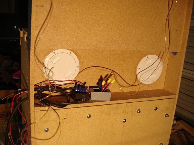
Really well built bench! I especially like the way you did the rear doors. Well supported all the way around. Individually removable...nice work!
Also, the accumulator is a great idea Tom..
Larry C
Posted:
Wed Mar 15, 2006 9:57 pmby larrycavan
Again..nice work. Couple of things to look at. It's hard to tell from the pic.
Did you compensate your inclined scale for the .826 red fluid?
Is the test pressure manometer compensates as well?
Using 1.0 SG fluid in the test pressure manometer, your inch increment markings should be at .5" increments if you want to read directly on one side of the U tube...
Larry
Posted:
Wed Mar 15, 2006 11:11 pmby SuperRunner
Thanks.
Is the scale I have for .826 fluid, or can I use water, or does it matter?
My test pressure is set to 1 inch increments, but I have it labled as if it was .5". I might put .5" lines in there later.
Posted:
Thu Mar 16, 2006 10:50 pmby Thomas Vaught
Because the U tube manometer goes up one leg and down the other leg you have to add the sum of the two legs. The other way is to make the 1 inch increments and then label them in 1/2 inch increments.
Trying to say a 1/2" movement on the one leg should be marked as 1 inch of test pressure. This way you only have to read one leg.
The inclined manometer fluid will move farther with the 8.26 fluid. Rocco's spreadsheet will allow you to adjust the well size to compensate.
Tom V.
Posted:
Fri Mar 17, 2006 12:26 amby SuperRunner
Yeah, that is how I have the U tube. Every real inch is 2" of water, so I don't have to add. Later I will put a small mark for the 1" of water.
I went and picked up some Dwyer fluid today, so all should be good, although I went ahead and ran some air throug my tubing with the reservoir still attached to get the water out and ...KABOOM!!!, guess I need to make another 
I begin calibration tomorrow....YEAH!!!!
Posted:
Sun Mar 19, 2006 12:33 pmby Thomas Vaught
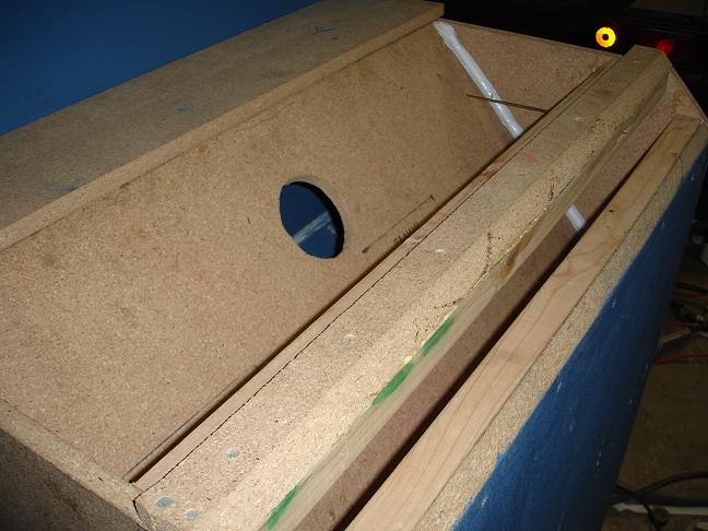
I think you are making great progress. The removable orifice deal should work ok too.
Tom V.
Posted:
Sun Apr 02, 2006 7:43 amby adi111
Where is test pressure brass tube located?
Picture please
Thanks
Posted:
Mon Apr 03, 2006 1:52 pmby SuperRunner
it is in a picture above. It sits just below the acrylic baffle. I may move it to above the baffle, but I don't think it will make any difference. I have already tried several other locations, and it hasn't changed.
Also, I have both tubes for my inclined manometer on one side of my cabinet in the upper corners about 1-2 inches away from the outer wall and about 3 inches below the top of each chamber. My inclined manometer is as steady as a rock. I get soo little movement it is hardly detectable.
Posted:
Mon Apr 03, 2006 9:41 pmby Thomas Vaught
You can make it move even less by putting a second tube with several small holes around the sensing tube. This eliminates any turbulence that may be in the cabinet from swirl in the plenums.
Tom V.